1 measur ing w o rk piece misalignment – HEIDENHAIN TNC 426B (280 472) Touch Probe Cycles User Manual
Page 42
30
3 Touch Probe Cycles for Automatic Workpiece Inspection
3.1 Measur
ing W
o
rk
piece Misalignment
U
U
U
U
First measuring point in the 1st axis
Q263
(absolute): coordinate of the first touch point in the
reference axis of the working plane.
U
U
U
U
First measuring point in the 2nd axis
Q264
(absolute): coordinate of the first touch point in the
minor axis of the working plane.
U
U
U
U
Second measuring point in the 1st axis
Q265
(absolute): coordinate of the second touch point in the
reference axis of the working plane
U
U
U
U
Second measuring point in the 2nd axis
Q266
(absolute): coordinate of the second touch point in the
minor axis of the working plane
U
U
U
U
Measuring axis
Q272: axis in the working plane in
which the measurement is to be made:
1: Reference axis = measuring axis
2: Minor axis = measuring axis
U
U
U
U
Traverse direction 1
Q267: direction in which the
probe is to approach the workpiece:
-1: Negative traverse direction
+1: Positive traverse direction
U
U
U
U
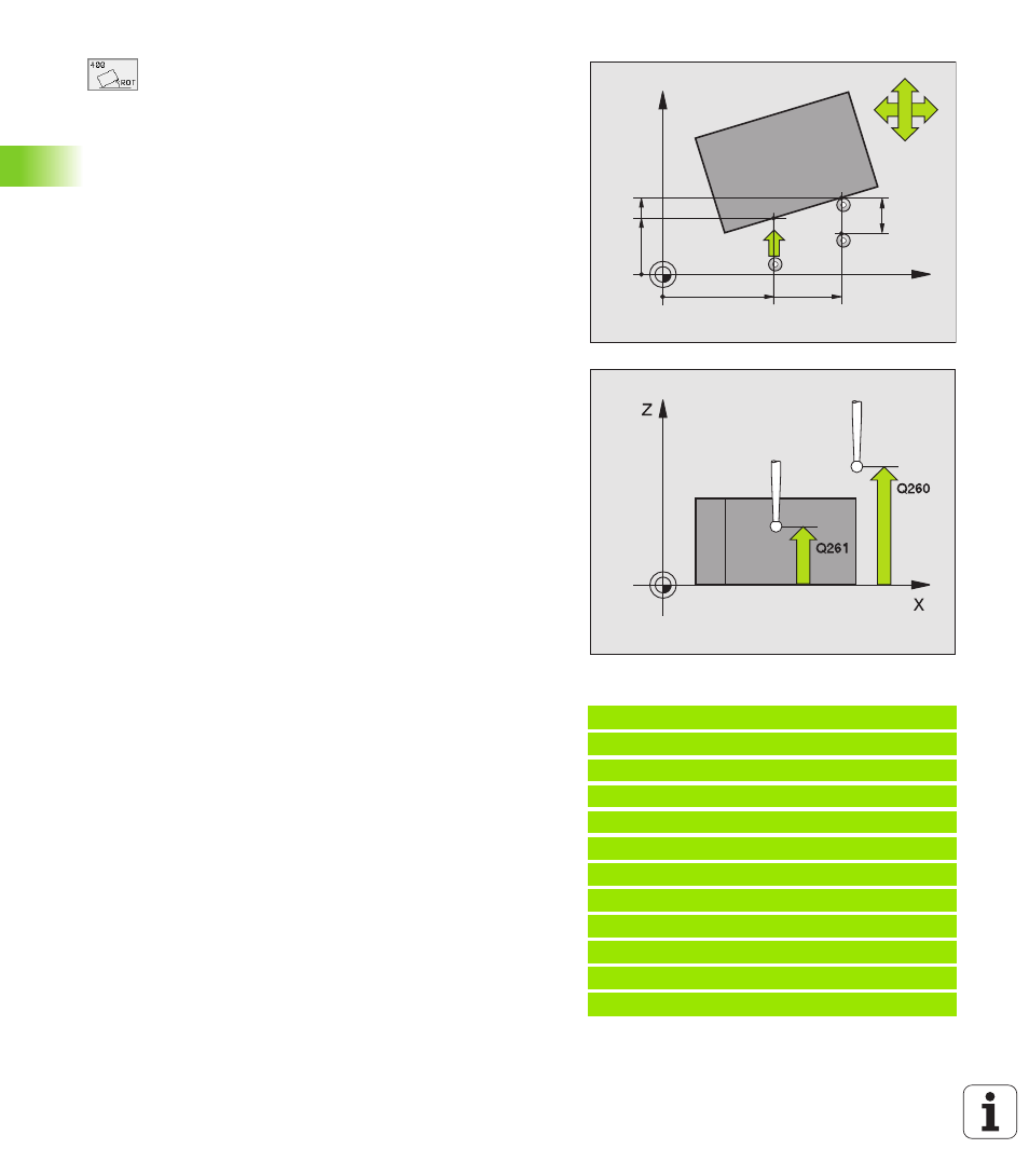
Measuring height in the touch probe axis
Q261
(absolute): coordinate of the ball tip center (= touch
point) in the touch probe axis in which the
measurement is to be made.
U
U
U
U
Setup clearance
Q320 (incremental): additional
distance between measuring point and ball tip. Q320
is added to MP6140.
U
U
U
U
Clearance height
Q260 (absolute): coordinate in the
touch probe axis at which no collision between tool
and workpiece (fixtures) can occur.
U
U
U
U
Traversing to clearance height
Q301: definition of
how the touch probe is to move between the
measuring points:
0: Move at measuring height between measuring
points
1: Move at clearance height between measuring
points
U
U
U
U
Default setting for basic rotation
Q307
(absolute): If the misalignment is to be measured
against a straight line other than the reference axis,
enter the angle of this reference line. The TNC will
then calculate the difference between the measured
value and the angle of the reference line for the basic
rotation.
Example: NC blocks
5 TCH PROBE 400 BASIC ROTATION
Q263=+10 ;1ST POINT 1ST AXIS
Q264=+3.5 ;1ST POINT 2ND AXIS
Q265=+25 ;2ND POINT 1ST AXIS
Q266=+2 ;2ND POINT 2ND AXIS
Q272=2 ;MEASURING AXIS
Q267=+1 ;TRAVERSE DIRECTION
Q261=-5 ;MEASURING HEIGHT
Q320=0 ;SET-UP CLEARANCE
Q260=+20 ;CLEARANCE HEIGHT
Q301=0 ;TRAVERSE TO CLEAR HEIGHT
Q307=+0 ;PRESET BASIC ROTATION
X
Y
Q266
Q264
Q263
Q272=1
Q265
Q272=2
+
–
–
+
Q267
MP6140
+
Q320