1 measur ing w o rk piece misalignment – HEIDENHAIN TNC 426B (280 472) Touch Probe Cycles User Manual
Page 46
34
3 Touch Probe Cycles for Automatic Workpiece Inspection
3.1 Measur
ing W
o
rk
piece Misalignment
U
U
U
U
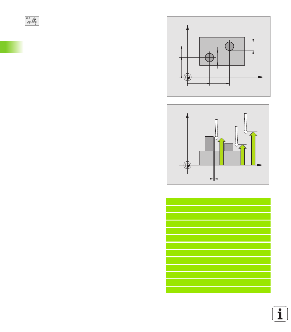
First stud: Center in 1st axis
Q268 (absolute):
center of the first stud in the reference axis of the
working plane.
U
U
U
U
First stud: Center in 2nd axis
Q269 (absolute):
center of the first stud in the minor axis of the
working plane.
U
U
U
U
Diameter of stud 1
Q313: approximate diameter of
the 1st stud. Enter a value that is more likely to be too
large than too small.
U
U
U
U
Measuring height 1 in the probe axis
Q261
(absolute): coordinate of the ball tip center (= touch
point in the touch probe axis) at which stud 1 is to be
measured.
U
U
U
U
Second stud: Center in 1st axis
Q270 (absolute):
center of the second stud in the reference axis of the
working plane.
U
U
U
U
Second stud: Center in 2nd axis
Q271 (absolute):
center of the second stud in the minor axis of the
working plane.
U
U
U
U
Diameter of stud 2
Q314: approximate diameter of
the 2nd stud. Enter a value that is more likely to be
too large than too small.
U
U
U
U
Measuring height 2 in the probe axis
Q315
(absolute): coordinate of the ball tip center (= touch
point in the touch probe axis) at which stud 2 is to be
measured.
U
U
U
U
Setup clearance
Q320 (incremental): additional
distance between measuring point and ball tip. Q320
is added to MP6140.
U
U
U
U
Clearance height
Q260 (absolute): coordinate in the
touch probe axis at which no collision between tool
and workpiece (fixtures) can occur.
U
U
U
U
Traversing to clearance height
Q301: definition of
how the touch probe is to move between the
measuring points:
0: Move at measuring height between measuring
points
1: Move at clearance height between measuring
points
U
U
U
U
Default setting for basic rotation
Q307
(absolute): If the misalignment is to be measured
against a straight line other than the reference axis,
enter the angle of this reference line. The TNC will
then calculate the difference between the measured
value and the angle of the reference line for the basic
rotation.
Example: NC blocks
5 TCH PROBE 402 ROT OF 2 STUDS
Q268=-37 ;1ST CENTER 1ST AXIS
Q269=+12 ;1ST CENTER 2ND AXIS
Q313=60 ;DIAMETER OF STUD 1
Q261=-5 ;MEASURING HEIGHT 1
Q270=+75 ;2ND CENTER 1ST AXIS
Q271=+20 ;2ND CENTER 2ND AXIS
Q314=60 ;DIAMETER STUD 2
Q315=-5 ;MEASURING HEIGHT 2
Q320=0 ;SET-UP CLEARANCE
Q260=+20 ;CLEARANCE HEIGHT
Q301=0 ;TRAVERSE TO CLEAR HEIGHT
Q307=+0 ;PRESET BASIC ROT.
X
Y
Q271
Q269
Q268
Q270
Q313
Q314
X
Z
Q261
Q260
Q315
MP6140
+
Q320