3 a u to matic w o rk piece measur ement – HEIDENHAIN TNC 426B (280 472) Touch Probe Cycles User Manual
Page 105
HEIDENHAIN TNC 426, TNC 430
93
3.3 A
u
to
matic W
o
rk
piece Measur
ement
U
U
U
U
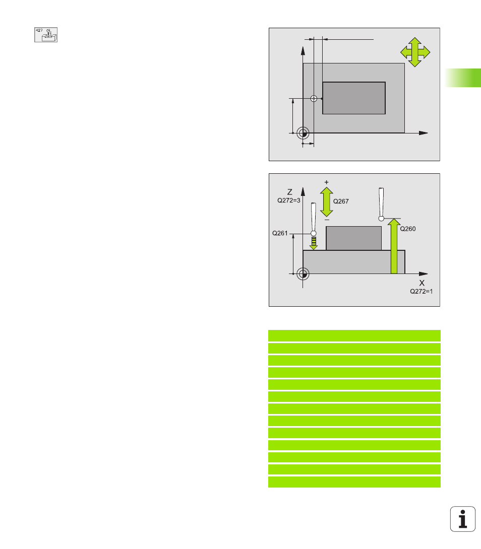
First measuring point in the 1st axis
Q263
(absolute): coordinate of the first touch point in the
reference axis of the working plane.
U
U
U
U
First measuring point in the 2nd axis
Q264
(absolute): coordinate of the first touch point in the
minor axis of the working plane.
U
U
U
U
Measuring height in the touch probe axis
Q261
(absolute): coordinate of the ball tip center (= touch
point) in the touch probe axis in which the
measurement is to be made.
U
U
U
U
Setup clearance
Q320 (incremental): additional
distance between measuring point and ball tip. Q320
is added to MP6140.
U
U
U
U
Measuring axis (1..3: 1=reference axis)
Q272:
axis in which the measurement is to be made:
1: Reference axis = measuring axis
2: Minor axis = measuring axis
3: Touch probe axis = measuring axis
U
U
U
U
Traverse direction 1
Q267: direction in which the
probe is to approach the workpiece:
-1: Negative traverse direction
+1: Positive traverse direction
U
U
U
U
Clearance height
Q260 (absolute): coordinate in the
touch probe axis at which no collision between tool
and workpiece (fixtures) can occur.
U
U
U
U
Measuring log
Q281: definition of whether the TNC is
to create a measuring log:
0: No measuring log
1: Generate measuring log: with the standard setting
the TNC saves the log file TCHPR427.TXT in the
directory in which your measuring program is also
stored.
U
U
U
U
Maximum dimension
Q288: maximum permissible
measured value.
U
U
U
U
minimum dimension
Q289: Minimum permissible
measured value
U
U
U
U
PGM stop if tolerance error
Q309: definition of
whether in the event of a violation of tolerance limits
the TNC is to interrupt the program run and output an
error message:
0: Do not interrupt program run, no error message
1: Interrupt program run, output an error message
U
U
U
U
Tool number for monitoring
Q330: definition of
whether the TNC is to monitor the tool (see “Tool
monitoring” on page 71):
0: Monitoring not active
>0: Tool number in the tool table TOOL.T
Example: NC blocks
5 TCH PROBE 427 MEASURE COORDINATE
Q263=+35 ;1ST POINT 1ST AXIS
Q264=+45 ;1ST POINT 2ND AXIS
Q261=+5 ;MEASURING HEIGHT
Q320=0 ;SET-UP CLEARANCE
Q272=3 ;MEASURING AXIS
Q267=-1 ;TRAVERSE DIRECTION
Q260=+20 ;CLEARANCE HEIGHT
Q281=1 ;MEASURING LOG
Q288=5.1 ;MAXIMUM DIMENSION
Q289=4.95 ;MINIMUM DIMENSION
Q309=0 ;PGM-STOP IF ERROR
Q330=0 ;TOOL NUMBER
X
Y
Q264
Q263
+
–
–
+
Q267
Q272=2
Q272=1
MP6140 + Q320