1 measur ing w o rk piece misalignment – HEIDENHAIN TNC 426B (280 472) Touch Probe Cycles User Manual
Page 47
HEIDENHAIN TNC 426, TNC 430
35
3.1 Measur
ing W
o
rk
piece Misalignment
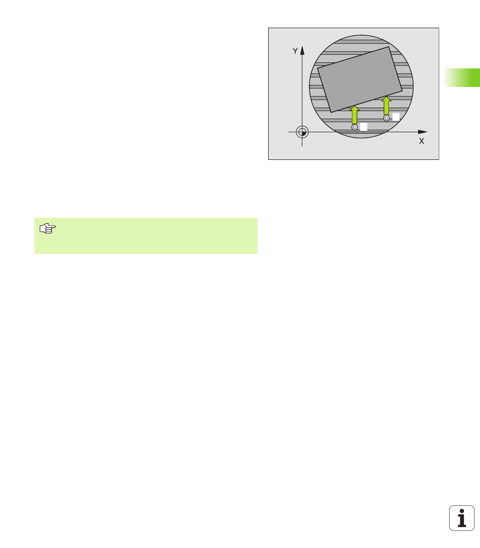
BASIC ROTATION compensation via rotary axis
(touch probe cycle 403, ISO: G403)
Touch probe cycle 403 determines a workpiece misalignment by
measuring two points, which must lie on a straight surface. The TNC
compensates the misalignment by rotating the A, B or C axis. The
workpiece can be clamped in any position on the rotary table.
1
The TNC positions the touch probe to the starting points at rapid
traverse (value from MP6150 or MP6361) following the positioning
logic (see “Running touch probe cycles” on page 7) to the
programmed starting point
1
. The TNC offsets the touch probe by
the safety clearance in the direction opposite the defined traverse
direction.
2
Then the touch probe moves to the entered measuring height and
probes the first touch point at the probing feed rate (MP6120 or
MP6360).
3
Then the touch probe moves to the next starting position
2
and
probes the second position.
4
The TNC returns the touch probe to the clearance height and
moves the rotary axis, which was defined in the cycle, by the
measured value.
Before programming, note the following:
Before a cycle definition you must have programmed a
tool call to define the touch probe axis.
11
2