Nv8280 switchover, 61 miranda router configurator, Possibly remotely – Grass Valley MRC v.1.2 User Manual
Page 71: User’s guide
61
Miranda Router Configurator
User’s Guide
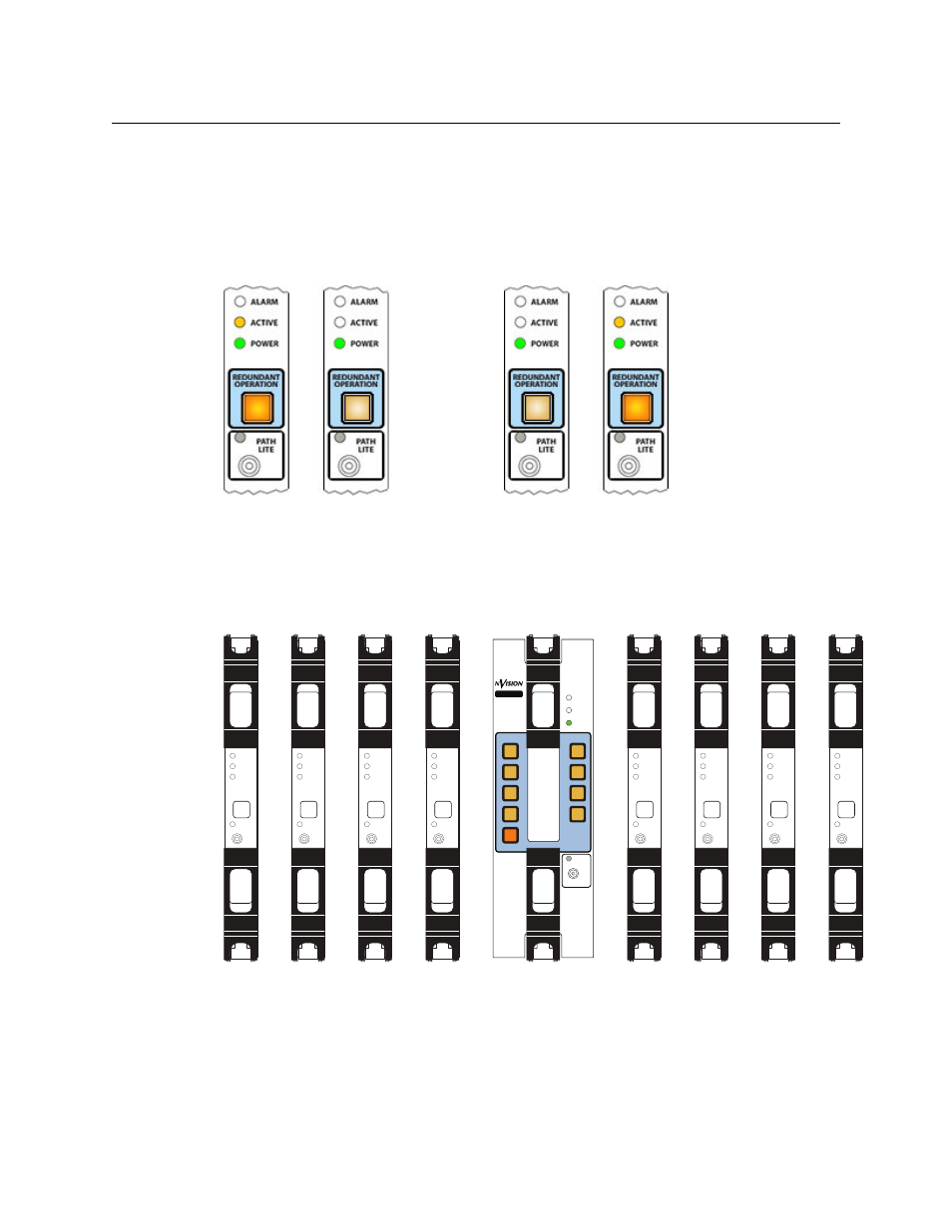
still powered up, its ‘Active’ LED turns off and its button turns dim. The second card’s active LED
turns on and its button turns bright.
The same holds true for the card in slot 2.
You can do the same kind of switching
—
possibly remotely
—
using the crosspoint card image
in the ‘Redundant Crosspoint’ page. These two figures show the different states of the cross-
point buttons:
NV8280 Switchover
The NV8280 has 10 crosspoint card slots. As viewed from the front of the router, slot 1 is on the
left and slot 10 is on the far right. The redundant crosspoint module occupies the two middle
slots, numbered 5 and 6:
The normal crosspoints are numbered 1–4 on the left and 7–10 on the right. Usually, the normal
crosspoint cards are active and their active LEDs are on and the redundant crosspoint card is in
standby mode, its ‘Active’ LED is off, and its ‘Standby’ button is bright.
If one of the normal cards (for instance, in slot 3) fails or you want to remove it from the frame,
press the button labeled 3 on the redundant crosspoint card. Immediately, the redundant card
takes over for the card in slot 3. If the card in slot 3 is still powered up, its ‘Active’ LED turns off.
Card 1 active; card 2 standby
Card 1 standby; card 2 active
144 X 144
3Gig
Redundant
XPT
NV8500
ALARM
ACTIVE
POWER
1
2
3
4
7
8
9
10
STANDBY
PATH
LITE
REDUNDANT
OPERATION
ALARM
ACTIVE
POWER
ALARM
ACTIVE
POWER
ALARM
ACTIVE
POWER
ALARM
ACTIVE
POWER
ALARM
ACTIVE
POWER
ALARM
ACTIVE
POWER
ALARM
ACTIVE
POWER
ALARM
ACTIVE
POWER