Verifying the configuration, Configuring sip calling through dns, Network requirements – H3C Technologies H3C MSR 5600 User Manual
Page 102: Configuration procedure

92
[RouterB-voice] sip
[RouterB-voice-sip] registrar 1 ip 192.168.2.3
[RouterB-voice-sip] proxy ip 192.168.2.3
[RouterB-voice-sip] quit
# Configure local number 2222 for POTS entity 2222 and bind FXS voice subscriber line 1/0 to
the POTS entity.
[RouterB-voice] dial-program
[RouterB-voice-dial] entity 2222 pots
[RouterB-voice-dial-entity2222] line 1/0
[RouterB-voice-dial-entity2222] match-template 2222
# Configure user name routerb, plaintext password 7890, and domain name server1.
[RouterB-voice-dial-entity2222] user routerB password simple 7890 realm server1
# Configure VoIP entity 2222 to get the call destination address from the proxy server and to
match number 1111.
[RouterB-voice-dial-entity2222] quit
[RouterB-voice-dial] entity 1111 voip
[RouterB-voice-dial-entity1111] address sip proxy
[RouterB-voice-dial-entity1111] match-template 1111
[RouterB-voice-dial-entity1111] quit
Verifying the configuration
# After the routers register phone numbers on the registrar, phone 1111 and phone 2222 can call each
other through the SIP proxy server.
# Executing the display voice sip register-status command can display the registration state for phones
1111 and 2222.
# Executing the display voice sip call command can display the SIP call information.
Configuring SIP calling through DNS
Network requirements
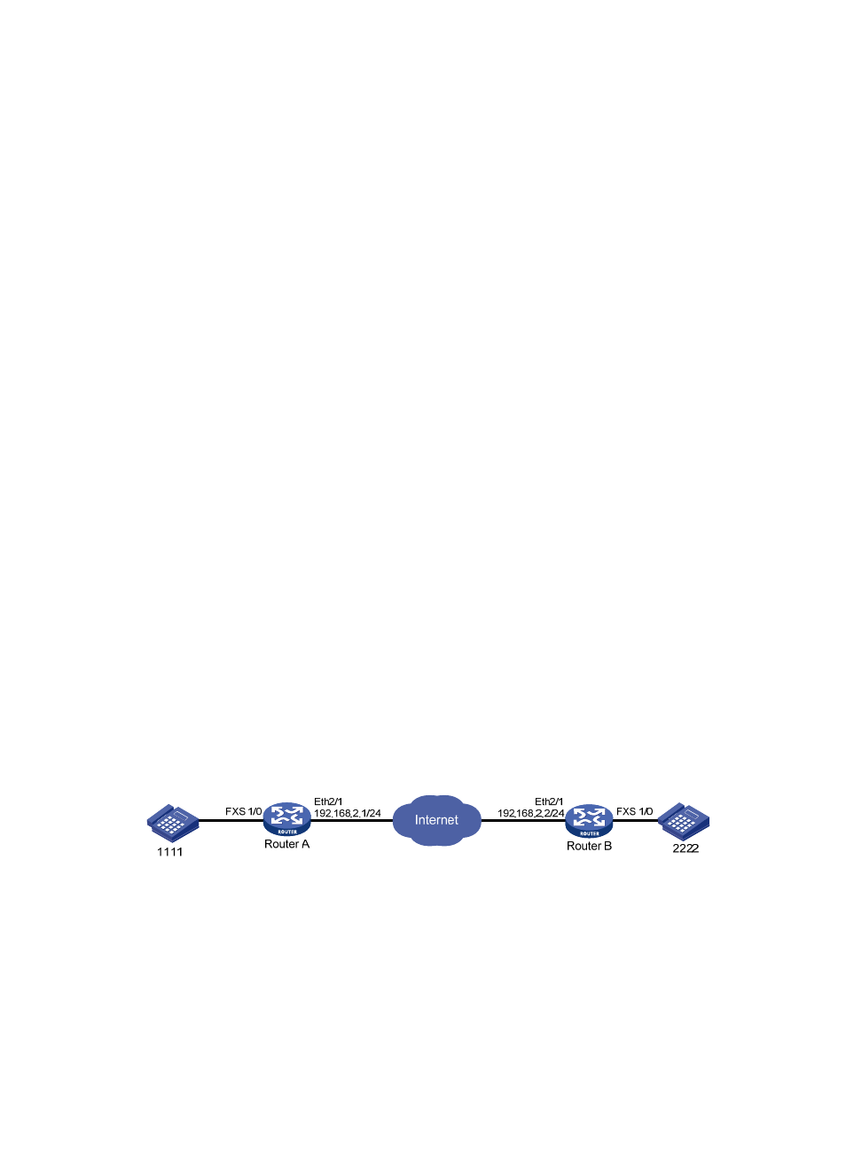
As shown in
, configure Router A to get the call destination address through DNS and configure
Router B to use a static call destination address so the phones 1111 and 2222 can call each other.
Figure 36 Network diagram
Configuration procedure
1.
Configure Router A:
# Configure an IP address for Ethernet 2/1.
[RouterA] interface ethernet 2/1
[RouterA-Ethernet2/1] ip address 192.168.2.1 255.255.255.0
[RouterA-Ethernet2/1] quit
