Network requirements, Configuration procedure – H3C Technologies H3C S10500 Series Switches User Manual
Page 66
51
Configuring BFD for RIP (bidirectional detection in BFD control
packet mode)
Network requirements
As shown in the following figure:
•
Switch A is connected to Switch C through Switch B. VLAN-interface 100 on Switch A,
VLAN-interface 200 on Switch C, and VLAN-interface 200 and VLAN-interface 100 on Switch B
run RIP process 1.
•
Configure a static route to Switch C on Switch A, and configure a static route to Switch A on Switch
C. Enable BFD on VLAN-interface 100 of Switch A and VLAN-interface 200 of Switch C.
•
Switch A is connected to Switch C through Switch D. VLAN-interface 300 on Switch A runs RIP
process 2; VLAN-interface 400 on Switch C, and VLAN-interface 300 and VLAN-interface 400 on
Switch D run RIP process 1.
•
Enable static route redistribution into RIP on Switch A and Switch C so that Switch A and Switch C
have routes to send to each other. Switch A learns the static route sent by Switch C, the outbound
interface is the interface connected to Switch B.
•
When the link between Switch B and Switch C fails, BFD can quickly detect the link failure and
notify it to RIP, and the BFD session goes down. In response, RIP deletes the neighbor relationship
with Switch C and the route information received from Switch C. Then, Switch A learns the static
route sent by Switch C, the outbound interface of the route is the interface connected to Switch D.
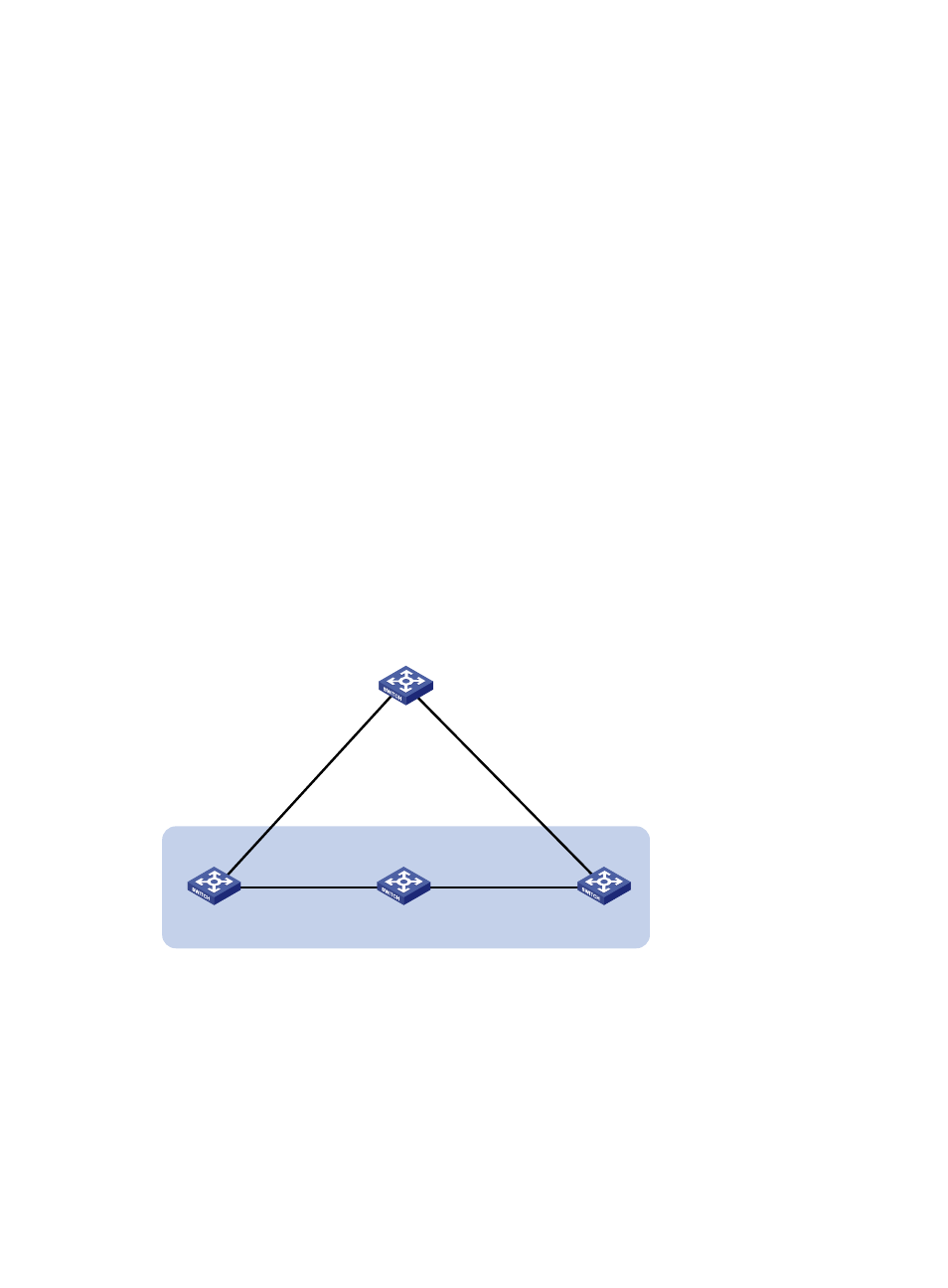
Figure 16 Network diagram for configuring BFD for RIP (bidirectional detection in BFD control packet
mode)
Switch C
Switch A
Vlan-int100
192.168.1.1/24
Vlan-int100
192.168.1.2/24
Switch B
Vlan-int200
192.168.2.1/24
BFD
Vlan-int200
192.168.2.2/24
Switch D
Vlan-int300
192.168.3.2/24
Vlan-int300
192.168.3.1/24
Vlan-int400
192.168.4.1/24
Vlan-int400
192.168.4.2/24
Configuration procedure
1.
Configure IP addresses for interfaces. (Details not shown)
2.
Configure RIP basic functions and enable static route redistribution into RIP so that Switch A and
Switch C have routes to send to each other.
# Configure Switch A.
[SwitchA] rip 1
[SwitchA-rip-1] network 192.168.1.0
[SwitchA-rip-1] peer 192.168.2.2