Bgp and igp synchronization configuration, Network requirements, Configuration procedure – H3C Technologies H3C S10500 Series Switches User Manual
Page 253
238
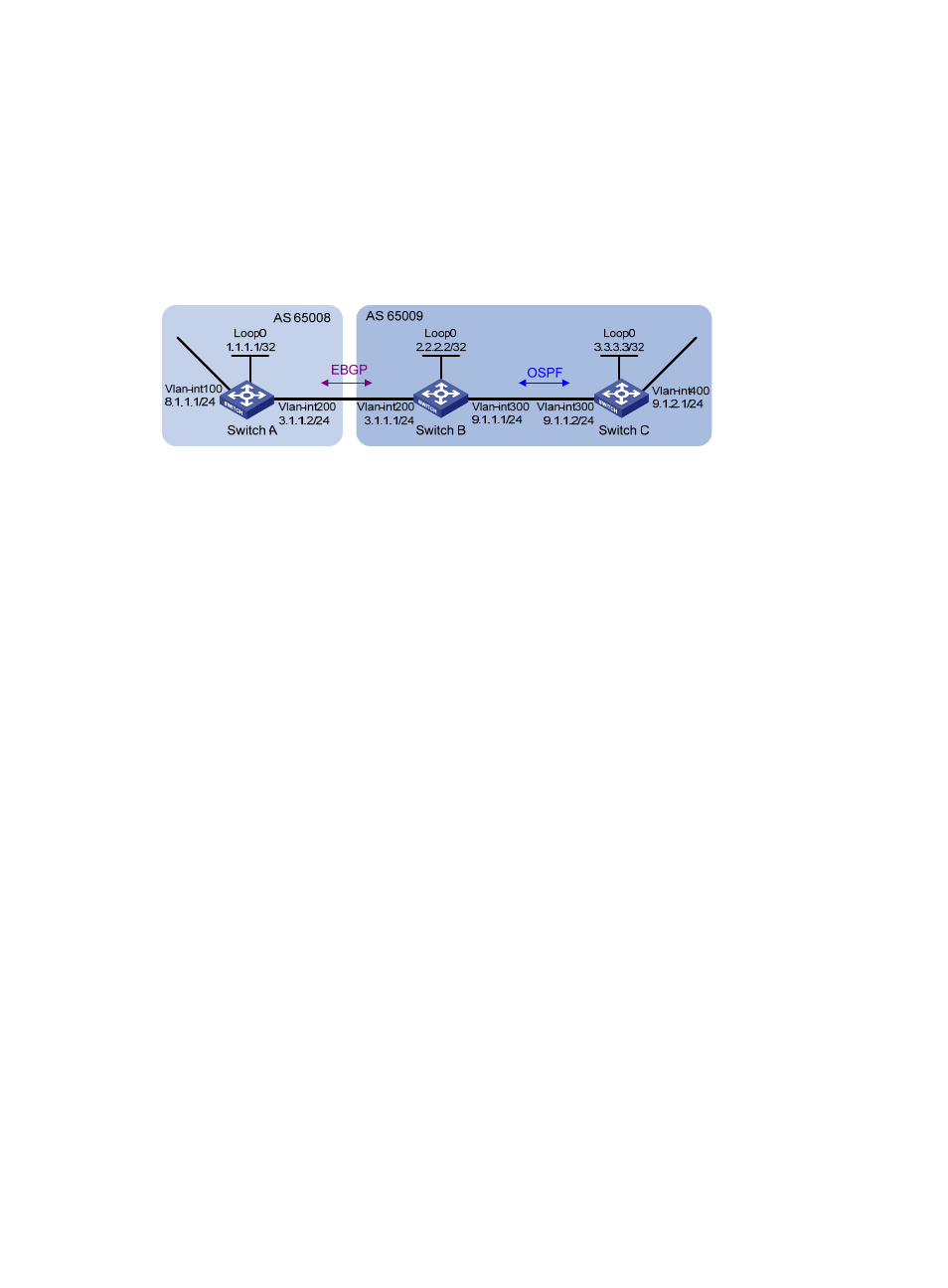
BGP and IGP synchronization configuration
Network requirements
As shown in
, all devices of company A belong to AS 65008, and all devices of company B
belong to AS 65009. AS 65008 and AS 65009 are connected through Switch A and Switch B. Switch
A must be able to access network 9.1.2.0/24 in AS 65009, and Switch C must access network 8.1.1.0/24
in AS 65008.
Figure 91 Network diagram for BGP and IGP synchronization
Configuration procedure
1.
Configure IP addresses for interfaces. (Details not shown)
2.
Configure OSPF.
Enable OSPF in AS 65009, so that Switch B can obtain the route to 9.1.2.0/24.
# Configure Switch B.
[SwitchB] ospf 1
[SwitchB-ospf-1] area 0
[SwitchB-ospf-1-area-0.0.0.0] network 2.2.2.2 0.0.0.0
[SwitchB-ospf-1-area-0.0.0.0] network 9.1.1.0 0.0.0.255
[SwitchB-ospf-1-area-0.0.0.0] quit
[SwitchB-ospf-1] quit
# Configure Switch C.
[SwitchC] ospf 1
[SwitchC-ospf-1] import-route direct
[SwitchC-ospf-1] area 0
[SwitchC-ospf-1-area-0.0.0.0] network 9.1.1.0 0.0.0.255
[SwitchC-ospf-1-area-0.0.0.0] quit
[SwitchC-ospf-1] quit
3.
Configure the eBGP connection.
Configure the eBGP connection and inject network 8.1.1.0/24 to the BGP routing table of Switch A, so
that Switch B can obtain the route to 8.1.1.0/24.
# Configure Switch A.
[SwitchA] bgp 65008
[SwitchA-bgp] router-id 1.1.1.1
[SwitchA-bgp] peer 3.1.1.1 as-number 65009
[SwitchA-bgp] network 8.1.1.0 24