Configuring bfd for ipv6 bgp, Network requirements, Configuration procedure – H3C Technologies H3C S10500 Series Switches User Manual
Page 361
346
[SwitchD-bgp-af-ipv6] peer 102::1 as-number 200
3.
Configure route reflector.
# Configure Switch C as a route reflector, and configure Switch B and Switch D as its clients.
[SwitchC-bgp-af-ipv6] peer 101::2 reflect-client
[SwitchC-bgp-af-ipv6] peer 102::2 reflect-client
Use the display bgp ipv6 routing-table command on Switch B and Switch D; both of them learned the
network 1::/64.
Configuring BFD for IPv6 BGP
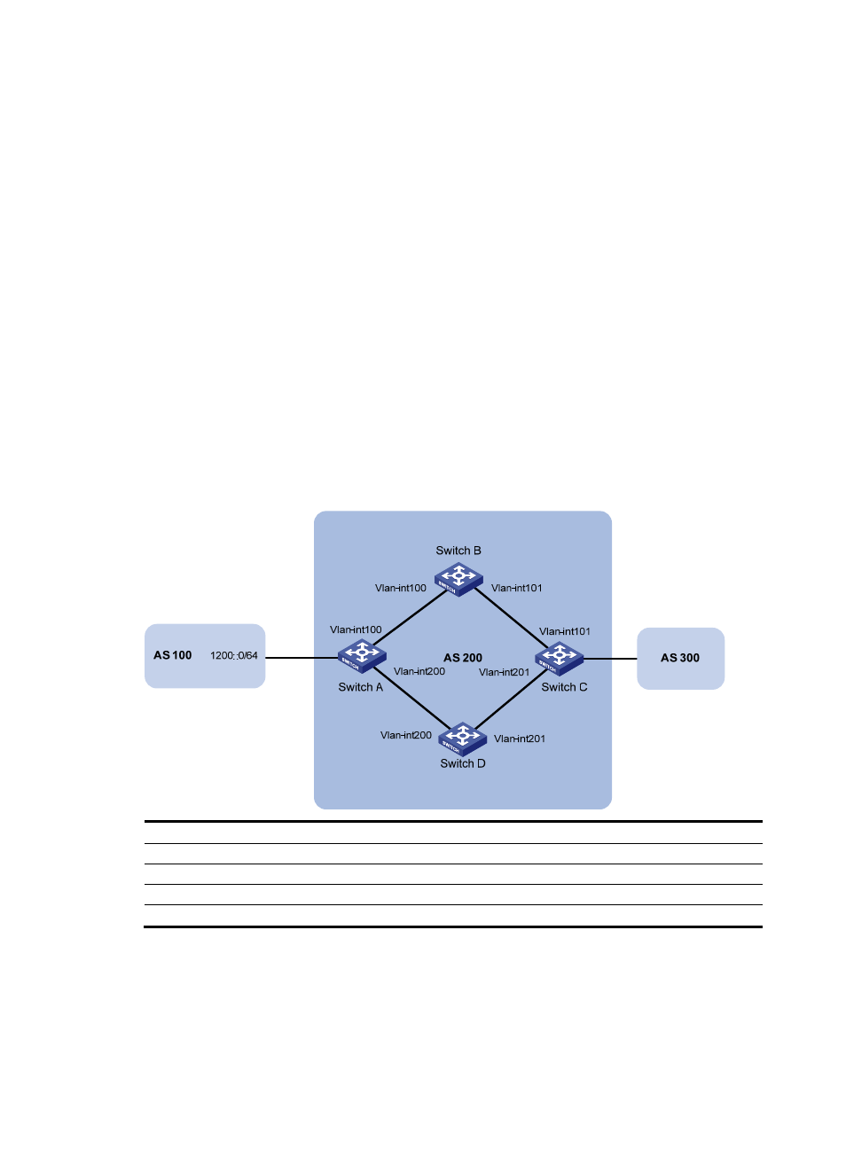
Network requirements
As shown in
,
•
Configure OSPFv3 as the IGP in AS 200.
•
Establish two iBGP connections between Switch A and Switch C. When both links are working,
Switch C adopts the link Switch A<—>Switch B<—>Switch C to exchange packets with network
1200::0/64. Configure BFD over the link. Then if the link fails, BFD can quickly detect the failure
and notify it to IPv6 BGP. Then the link Switch A<—>Switch D<—>Switch C takes effect
immediately.
Figure 115 Network diagram for BFD configuration for IPv6 BGP
Device Interface IP
address
Device Interface IP
address
Switch A
Vlan-int100
3000::1/64
Switch C
Vlan-int101
3001::3/64
Vlan-int200 2000::1/64
Vlan-int201 2001::3/64
Switch B
Vlan-int100
3000::2/64
Switch D
Vlan-int200
2000::2/64
Vlan-int101 3001::2/64
Vlan-int201 2001::2/64
Configuration procedure
1.
Configure IP addresses for interfaces. (Details not shown)
2.
Configure OSPFv3 to ensure that Switch A and Switch C are reachable to each other. (Details not
shown)