Configuration procedure, Verification, Network requirements – H3C Technologies H3C S10500 Series Switches User Manual
Page 394
379
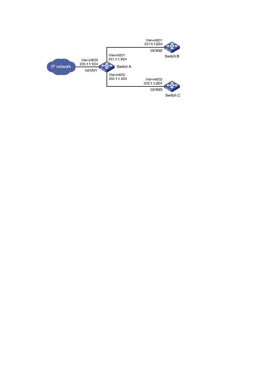
Figure 121 Network diagram for IPv4 PBR configuration
Configuration procedure
# Configure ACL 2000.
[SwitchA] acl number 2000
[SwitchA-acl-basic-2000] rule 0 permit source any
[SwitchA-acl-basic-2000] quit
# Define a match criterion for class a to match ACL 2000.
[SwitchA] traffic classifier a
[SwitchA-classifier-a] if-match acl 2000
[SwitchA-classifier-a] quit
# Configure the action of redirecting traffic to the next hop 202.1.1.2 for behavior a.
[SwitchA] traffic behavior a
[SwitchA-behavior-a] redirect next-hop 202.1.1.2
[SwitchA-behavior-a] quit
# Associate class a with behavior a in QoS policy a.
[SwitchA] qos policy a
[SwitchA-qospolicy-a] classifier a behavior a
[SwitchA-qospolicy-a] quit
# Apply QoS policy a to the incoming traffic of GigabitEthernet 1/0/1.
[SwitchA] interface gigabitethernet 1/0/1
[SwitchA-GigabitEthernet1/0/1] qos apply policy a inbound
Verification
After completing the configuration, verify that when Switch A receives packets with destination IP address
201.1.1.2, it forwards the packets to Switch C instead of Switch B.
IPv6 PBR configuration example (using a QoS policy)
Network requirements
As shown in
, redirect all packets received on GigabitEthernet 1/0/1 of Switch A to the next
hop 202::2.