Static route frr configuration example, Network requirements, Configuration procedure – H3C Technologies H3C S10500 Series Switches User Manual
Page 29
14
2 <1 ms <1 ms <1 ms 1.1.4.1
3 1 ms <1 ms <1 ms 1.1.2.2
Trace complete.
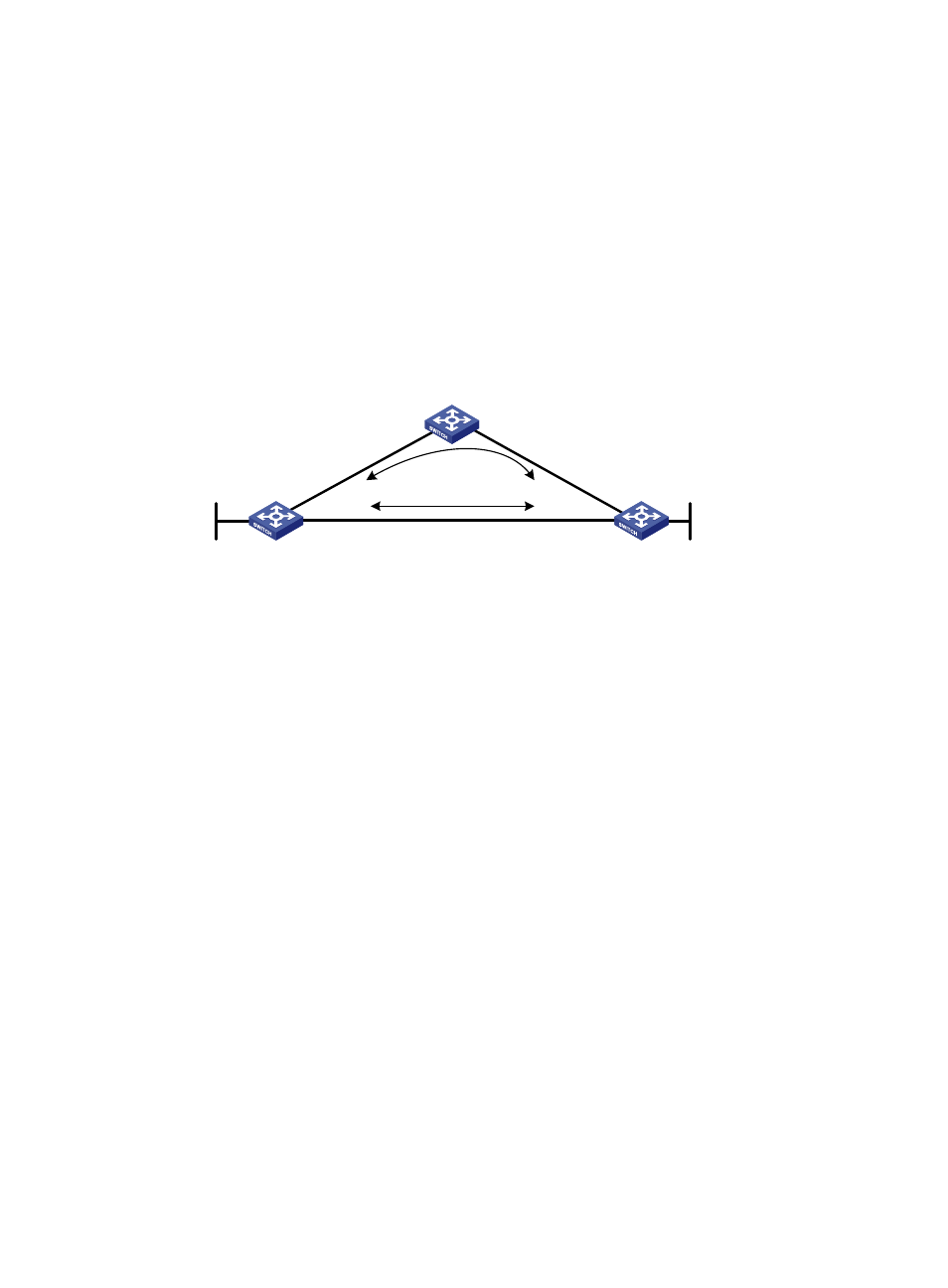
Static route FRR configuration example
Network requirements
Switch S, Switch A, and Switch D are interconnected through static routes, as illustrated in
Configure static route FRR so that when the link between Switch S and Switch D fails, traffic can be
switched to Link B immediately.
Figure 3 Network diagram for static route FRR configuration
Switch S
Switch D
Switch A
Loop 0
1.1.1.1/32
Vla
n-i
nt1
00
12
.12
.12
.1/
24
Vlan-int200
13.13.13.1/24
Vlan-int200
13.13.13.2/24
Vla
n-i
nt1
00
12
.12
.12
.2/
24
Vla
n-in
t10
1
24.2
4.2
4.2
/24
Vla
n-in
t10
1
24.2
4.2
4.4
/24
Loop 0
4.4.4.4/32
Link A
Link B
Configuration procedure
1.
Configure IP addresses for the interfaces on each switch and configure static routes.
Follow
to configure the IP address and subnet mask of each interface on the switches. (Details
not shown)
Configure static routes on Switch S, Switch A, and Switch D so that Switch S can reach Loopback 0 on
Switch D and Switch D can reach Loopback 0 on Switch S.
# Configure a static route on Switch S.
[SwitchS] ip route-static 4.4.4.4 32 vlan-interface 200 13.13.13.2
[SwitchS] ip route-static 4.4.4.4 32 vlan-interface 100 12.12.12.2 preference 65
# Configure a static route on Switch D.
[SwitchD] ip route-static 1.1.1.1 32 vlan-interface 200 13.13.13.1
[SwitchD] ip route-static 1.1.1.1 32 vlan-interface 101 24.24.24.2 preference 65
# Configure a static route on Switch A.
[SwitchA] ip route-static 4.4.4.4 32 vlan-interface 101 24.24.24.4
[SwitchA] ip route-static 1.1.1.1 32 vlan-interface 100 12.12.12.1
2.
Configure static route FRR.
# Configure Switch S.
[SwitchS] bfd echo-source-ip 1.1.1.1
[SwitchS] ip ip-prefix abc index 10 permit 4.4.4.4 32
[SwitchS] route-policy frr permit node 10
[SwitchS-route-policy] if-match ip-prefix abc