Configuration procedure – H3C Technologies H3C S10500 Series Switches User Manual
Page 380
365
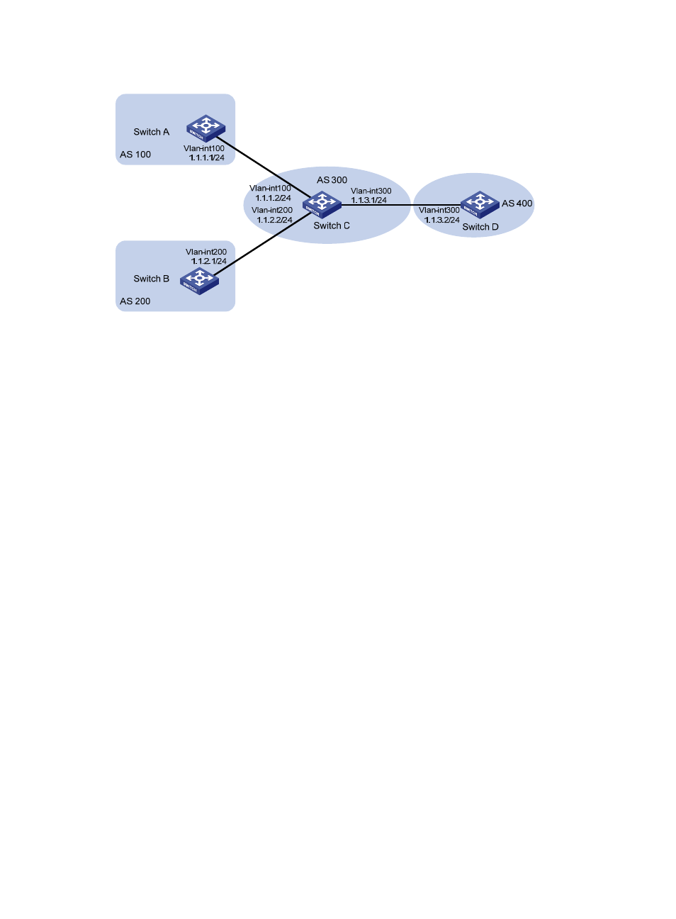
Figure 118 Routing policy configuration to filter received BGP routes
Configuration procedure
1.
Configure IP addresses for the interfaces. (Details not shown)
2.
Configure BGP.
# Configure Switch A.
[SwitchA] bgp 100
[SwitchA-bgp] router-id 1.1.1.1
[SwitchA-bgp] peer 1.1.1.2 as-number 300
# Configure Switch B.
[SwitchB] bgp 200
[SwitchB-bgp] router-id 2.2.2.2
[SwitchB-bgp] peer 1.1.2.2 as-number 300
# Configure Switch C.
[SwitchC] bgp 300
[SwitchC-bgp] router-id 3.3.3.3
[SwitchC-bgp] peer 1.1.1.1 as-number 100
[SwitchC-bgp] peer 1.1.2.1 as-number 200
[SwitchC-bgp] peer 1.1.3.2 as-number 400
# Configure Switch D.
[SwitchD] bgp 400
[SwitchD-bgp] router-id 4.4.4.4
[SwitchD-bgp] peer 1.1.3.1 as-number 300
[SwitchD-bgp] quit
# On Switch A, inject routes 4.4.4.4/24, 5.5.5.5/24, and 6.6.6.6/24 to BGP.
[SwitchA-bgp] network 4.4.4.4 24
[SwitchA-bgp] network 5.5.5.5 24