Network requirements, Configuration procedure – H3C Technologies H3C S10500 Series Switches User Manual
Page 63
48
Tag: 0
Configuring BFD for RIP (single-hop detection in BFD echo
packet mode)
Network requirements
As shown in the following figure:
•
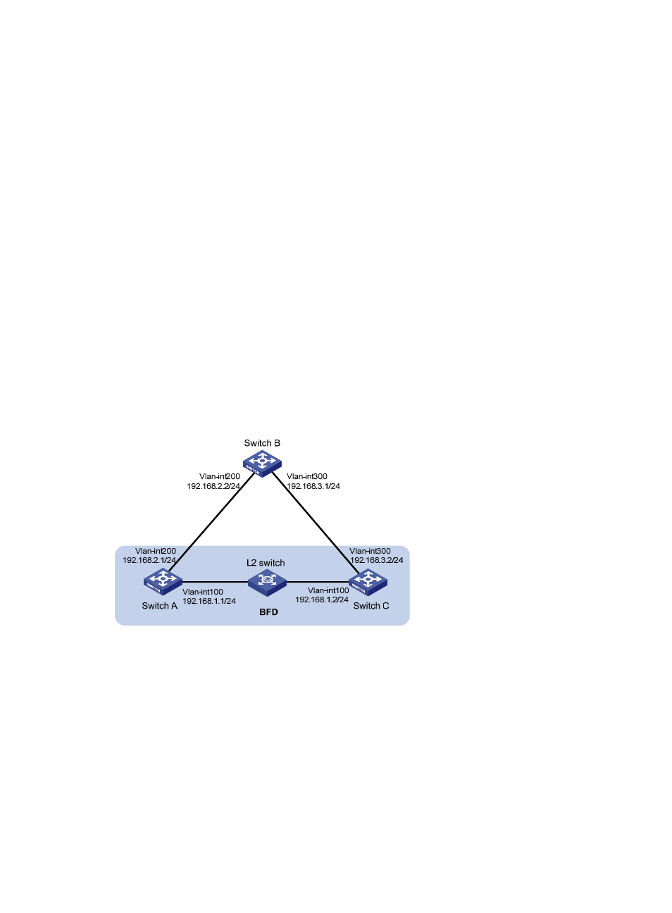
Switch A and Switch C are interconnected through a Layer 2 switch. VLAN-interface 100 of the two
switches runs RIP process 1, BFD is enabled on VLAN-interface 100 of Switch A.
•
Switch A is connected to Switch C through Switch B. VLAN-interface 200 on Switch A runs RIP
process 2; VLAN-interface 300 on Switch C, and VLAN-interface 200 and VLAN-interface 300 on
Switch B run RIP process 1.
•
Configure a static route and enable static route redistribution into RIP on Switch C. Switch A learns
the static route sent by Switch C, the outbound interface of the route is the interface connected to the
Layer 2 switch.
•
When the link between Switch C and the Layer 2 switch fails, BFD can quickly detect the link failure
and notify it to RIP, and the BFD session goes down. In response, RIP deletes the neighbor
relationship with Switch C and the route information received from Switch C. Then, Switch A learns
the static route sent by Switch C with the outbound interface being the interface connected to Switch
B.
Figure 15 Network diagram for configuring BFD for RIP (single-hop detection in BFD echo packet mode)
Configuration procedure
1.
Configure IP addresses for interfaces. (Details not shown)
2.
Configure RIP basic functions.
# Configure Switch A.
[SwitchA] rip 1
[SwitchA-rip-1] network 192.168.1.0
[SwitchA-rip-1] quit
[SwitchA] interface vlan-interface 100
[SwitchA-Vlan-interface100] rip bfd enable
[SwitchA-Vlan-interface100] quit
[SwitchA] rip 2