Bgp community configuration, Network requirements, Configuration procedure – H3C Technologies H3C S10500 Series Switches User Manual
Page 258
243
Status codes: * - valid, ^ - VPNv4 best, > - best, d - damped,
h - history, i - internal, s - suppressed, S - Stale
Origin : i - IGP, e - EGP, ? - incomplete
Network NextHop MED LocPrf PrefVal Path/Ogn
*> 8.1.1.0/24 0.0.0.0 0 0 i
*> 9.1.1.0/24 3.1.1.1 0 0 65009i
*> 3.1.2.1 0 0 65009i
•
The route 9.1.1.0/24 has two next hops 3.1.1.1 and 3.1.2.1, both of which are marked with a
greater-than sign (>), indicating they are the best routes.
•
By using the display ip routing-table command, you can find two routes to 9.1.1.0/24: one with next
hop 3.1.1.1 and outbound interface VLAN-interface 200, the other with next hop 3.1.2.1 and
outbound interface VLAN-interface 300.
BGP community configuration
Network requirements
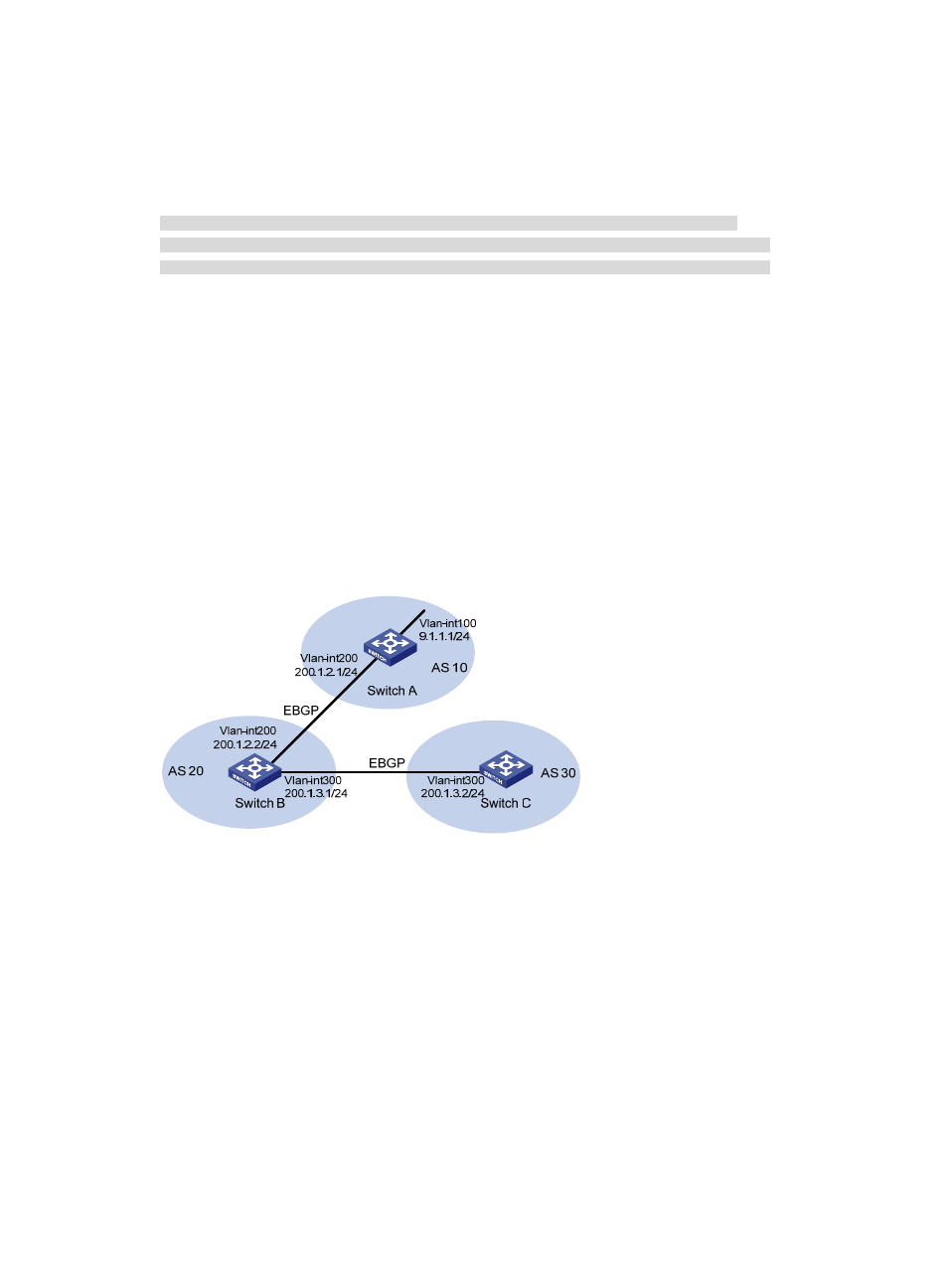
As shown in
, Switch B establishes eBGP connections with Switch A and C. Configure
No_Export community attribute on Switch A to make routes from AS 10 not advertised by AS 20 to any
other AS.
Figure 93 Network diagram for BGP community configuration
Configuration procedure
1.
Configure IP addresses for interfaces. (Details not shown)
2.
Configure eBGP.
# Configure Switch A.
[SwitchA] bgp 10
[SwitchA-bgp] router-id 1.1.1.1
[SwitchA-bgp] peer 200.1.2.2 as-number 20
[SwitchA-bgp] network 9.1.1.0 255.255.255.0
[SwitchA-bgp] quit
# Configure Switch B.
[SwitchB] bgp 20