Network requirements, Configuration procedure – H3C Technologies H3C S10500 Series Switches User Manual
Page 31
16
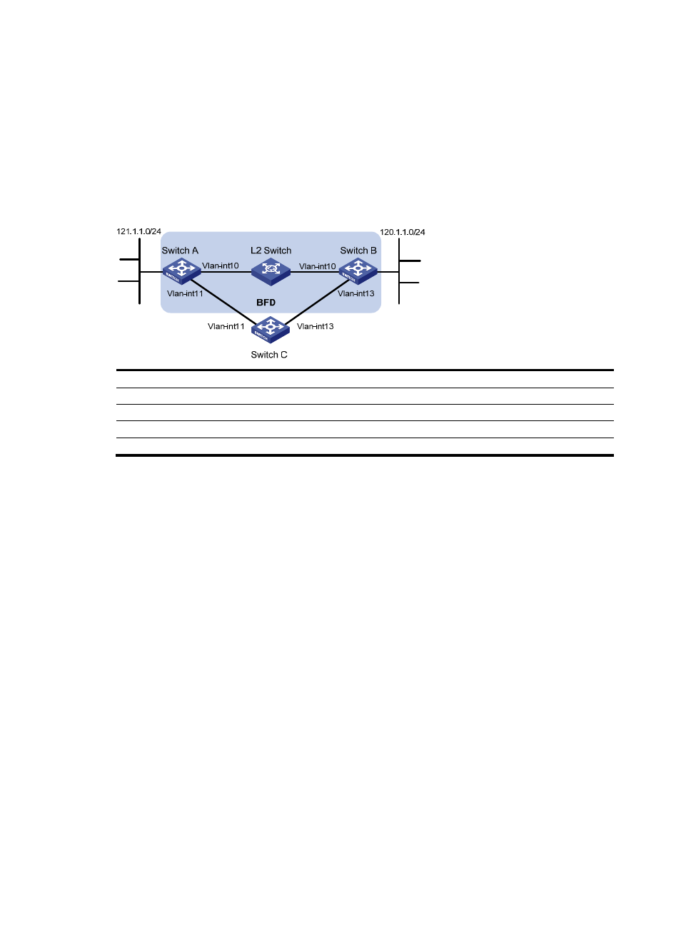
BFD for static routes configuration example (direct session)
Network requirements
As shown in
, configure static routes to subnet 120.1.1.0/24 on Switch A, static routes to subnet
121.1.1.0/24 on Switch B, and static routes to subnets 120.1.1.0/24 and 121.1.1.0/24 on Switch C.
Enable BFD so that when the link between Switch A and Switch B through the Layer 2 switch fails, BFD
can detect the failure immediately and Switch A and Switch B can communicate through Switch C.
Figure 4 Network diagram for configuring BFD for static routes (direct session)
Device
Interface
IP address
Device
Interface
IP address
Switch A
Vlan-int10
12.1.1.1/24
Switch B
Vlan-int10
12.1.1.2/24
Vlan-int11
10.1.1.102/24
Vlan-int13
13.1.1.1/24
Switch
C
Vlan-int11
10.1.1.100/24
Vlan-int13
13.1.1.2/24
Configuration procedure
1.
Configure IP addresses for the interfaces. (Details not shown)
2.
Configure BFD.
# Configure static routes on Switch A and enable BFD control packet mode for the static route through the
Layer 2 switch.
[SwitchA] interface vlan-interface10
[SwitchA-vlan-interface10] bfd min-transmit-interval 500
[SwitchA-vlan-interface10] bfd min-receive-interval 500
[SwitchA-vlan-interface10] bfd detect-multiplier 9
[SwitchA-vlan-interface10] quit
[SwitchA] ip route-static 120.1.1.0 24 vlan-interface 10 12.1.1.2 bfd control-packet
[SwitchA] ip route-static 120.1.1.0 24 vlan-interface 11 10.1.1.100 preference 65
[SwitchA] quit
# Configure static routes on Switch B and enable BFD control packet mode for the static route through the
Layer 2 switch.
[SwitchB] interface vlan-interface10
[SwitchB-vlan-interface10] bfd min-transmit-interval 500
[SwitchB-vlan-interface10] bfd min-receive-interval 500
[SwitchB-vlan-interface10] bfd detect-multiplier 9
[SwitchB-vlan-interface10]] quit