Is-is graceful restart configuration example, Network requirements, Configuration procedure – H3C Technologies H3C S10500 Series Switches User Manual
Page 195
180
192.168.0.0/24 10 NULL VLAN300 Direct D/L/-
10.1.4.0/24 10 NULL VLAN300 192.168.0.2 R/L/-
10.1.5.0/24 20 NULL VLAN300 192.168.0.2 R/L/-
10.1.6.0/24 20 NULL VLAN300 192.168.0.2 R/L/-
Flags: D-Direct, R-Added to RM, L-Advertised in LSPs, U-Up/Down Bit Set
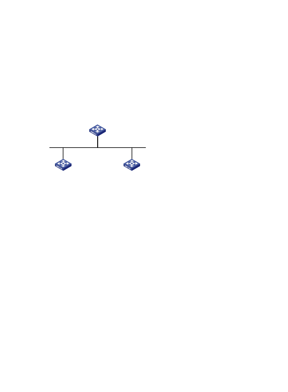
IS-IS Graceful Restart configuration example
Network requirements
Switch A, Switch B, and Switch C belong to the same IS-IS routing domain, as illustrated in
Figure 67 Network diagram for IS-IS GR configuration
Vlan-int100
10.0.0.1/24
Vlan-int100
10.0.0.3/24
Vlan-int100
10.0.0.2/24
GR helper
GR helper
GR restarter
Switch A
Switch C
Switch B
Configuration procedure
1.
Configure IP addresses of the interfaces on each switch and configure IS-IS.
Follow
to configure the IP address and subnet mask of each interface. (Details not shown)
Configure IS-IS on the switches, ensuring that Switch A, Switch B and Switch C can communicate with
each other at layer 3 and dynamic route update can be implemented among them with IS-IS. (Details not
shown)
2.
Configure IS-IS Graceful Restart.
# Enable IS-IS Graceful Restart on Switch A and configure the Graceful Restart Interval.
[SwitchA] isis 1
[SwitchA-isis-1] graceful-restart
[SwitchA-isis-1] graceful-restart interval 150
[SwitchA-isis-1] return
Configurations for Switch B and Switch C are similar; therefore, details are not shown.
3.
Verify the configuration.
After Router A establishes adjacencies with Router B and Router C, they begin to exchange routing
information. Restart IS-IS on Router A, which enters into the restart state and sends connection requests to
its neighbors through the Graceful Restart mechanism to synchronize the LSDB. Using the display isis
graceful-restart status command can display the IS-IS GR status on Router A.
# Restart the IS-IS process on Switch A.
Warning : Reset ISIS process? [Y/N]:y