Bgp gr configuration, Network requirements, Configuration procedure – H3C Technologies H3C S10500 Series Switches User Manual
Page 269
254
Route 1.0.0.0/8 from Switch D to Switch C is the optimal.
BGP GR configuration
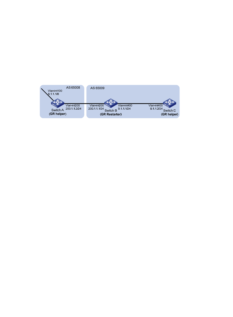
Network requirements
All switches run BGP in
. Between Switch A and Switch B is an eBGP connection. Switch B and
Switch C are connected over an iBGP connection. Enable GR capability for BGP so that the
communication between Switch A and Switch C is not affected when an active/standby MPU switchover
occurs on Switch B.
Figure 97 Network diagram for BGP GR configuration
Configuration procedure
1.
Configure Switch A.
# Configure IP addresses for interfaces. (Details not shown)
# Configure the eBGP connection.
[SwitchA] bgp 65008
[SwitchA-bgp] router-id 1.1.1.1
[SwitchA-bgp] peer 200.1.1.1 as-number 65009
# Inject network 8.0.0.0/8 to the BGP routing table.
[SwitchA-bgp] network 8.0.0.0
# Enable GR capability for BGP.
[SwitchA-bgp] graceful-restart
2.
Configure Switch B.
# Configure IP addresses for interfaces. (Details not shown)
# Configure the eBGP connection.
[SwitchB] bgp 65009
[SwitchB-bgp] router-id 2.2.2.2
[SwitchB-bgp] peer 200.1.1.2 as-number 65008
# Configure the iBGP connection.
[SwitchB-bgp] peer 9.1.1.2 as-number 65009
# Inject networks 200.1.1.0/24 and 9.1.1.0/24 to the BGP routing table.
[SwitchB-bgp] network 200.1.1.0 24
[SwitchB-bgp] network 9.1.1.0 24
# Enable GR capability for BGP.
[SwitchB-bgp] graceful-restart