Configuration procedure – H3C Technologies H3C S10500 Series Switches User Manual
Page 256
241
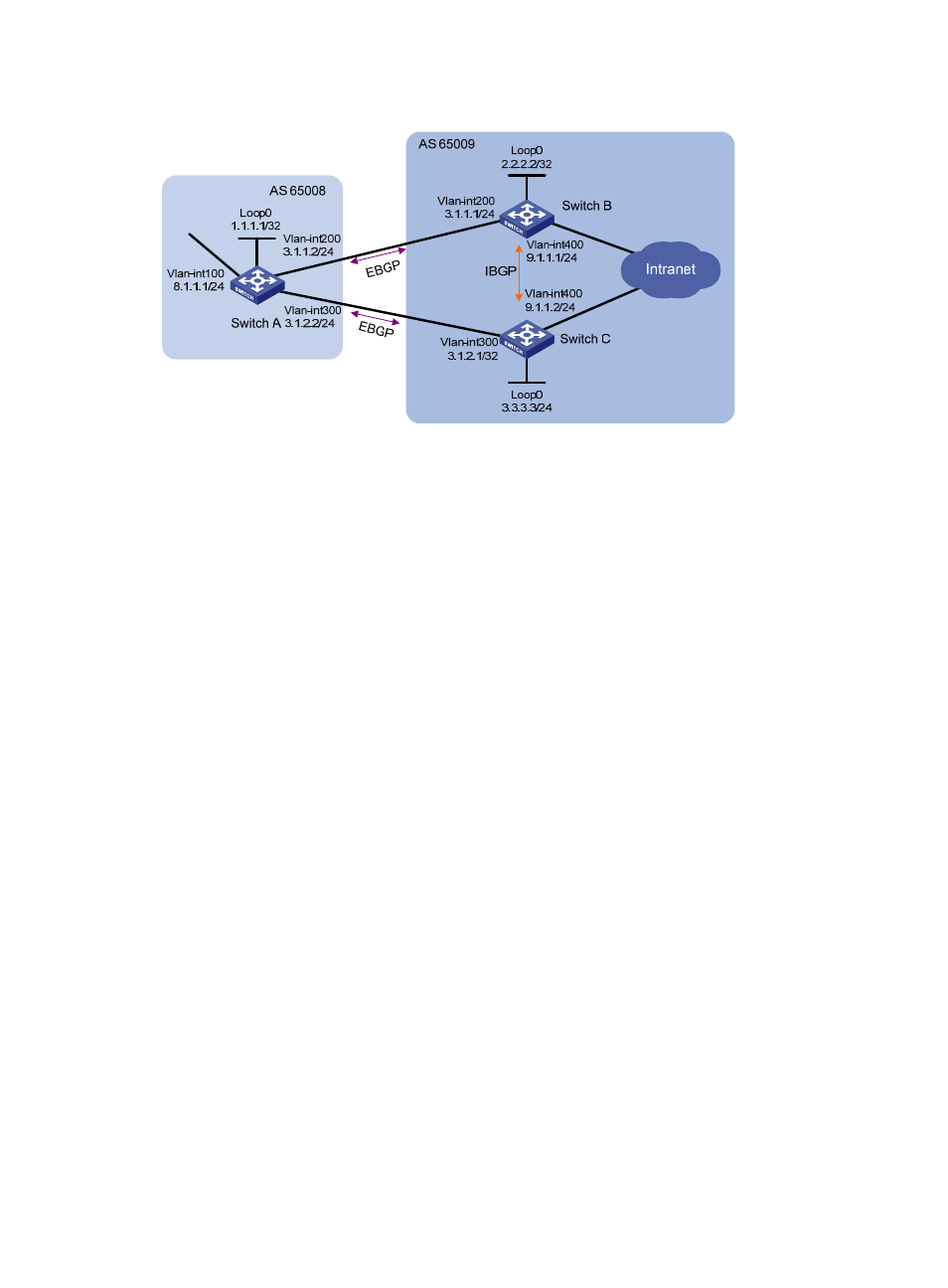
Figure 92 Network diagram for BGP load balancing configuration
Configuration procedure
1.
Configure IP addresses for interfaces. (Details not shown)
2.
Configure BGP connections.
•
On Switch A, establish eBGP connections with Switch B and Switch C respectively; configure BGP
to advertise network 8.1.1.0/24 to Switch B and Switch C, so that Switch B and Switch C can access
the internal network connected to Switch A.
•
On Switch B, establish an eBGP connection with Switch A and an iBGP connection with Switch C;
configure BGP to advertise network 9.1.1.0/24 to Switch A, so that Switch A can access the intranet
through Switch B; configure a static route to interface loopback 0 on Switch C (or use a routing
protocol like OSPF) to establish the iBGP connection.
•
On Switch C, establish an eBGP connection with Switch A and an iBGP connection with Switch B;
configure BGP to advertise network 9.1.1.0/24 to Switch A, so that Switch A can access the intranet
through Switch C; configure a static route to interface loopback 0 on Switch B (or use another
protocol like OSPF) to establish the iBGP connection.
# Configure Switch A.
[SwitchA] bgp 65008
[SwitchA-bgp] router-id 1.1.1.1
[SwitchA-bgp] peer 3.1.1.1 as-number 65009
[SwitchA-bgp] peer 3.1.2.1 as-number 65009
[SwitchA-bgp] network 8.1.1.1 24
[SwitchA-bgp] quit
# Configure Switch B.
[SwitchB] bgp 65009
[SwitchB-bgp] router-id 2.2.2.2
[SwitchB-bgp] peer 3.1.1.2 as-number 65008
[SwitchB-bgp] peer 3.3.3.3 as-number 65009
[SwitchB-bgp] peer 3.3.3.3 connect-interface loopback 0
[SwitchB-bgp] network 9.1.1.0 255.255.255.0
[SwitchB-bgp] quit