Advanced setup "device status – ARAG Bravo 400S Seletron User Manual
Page 60
60
ADVANCED SETUP
"DEVICE STATUS"
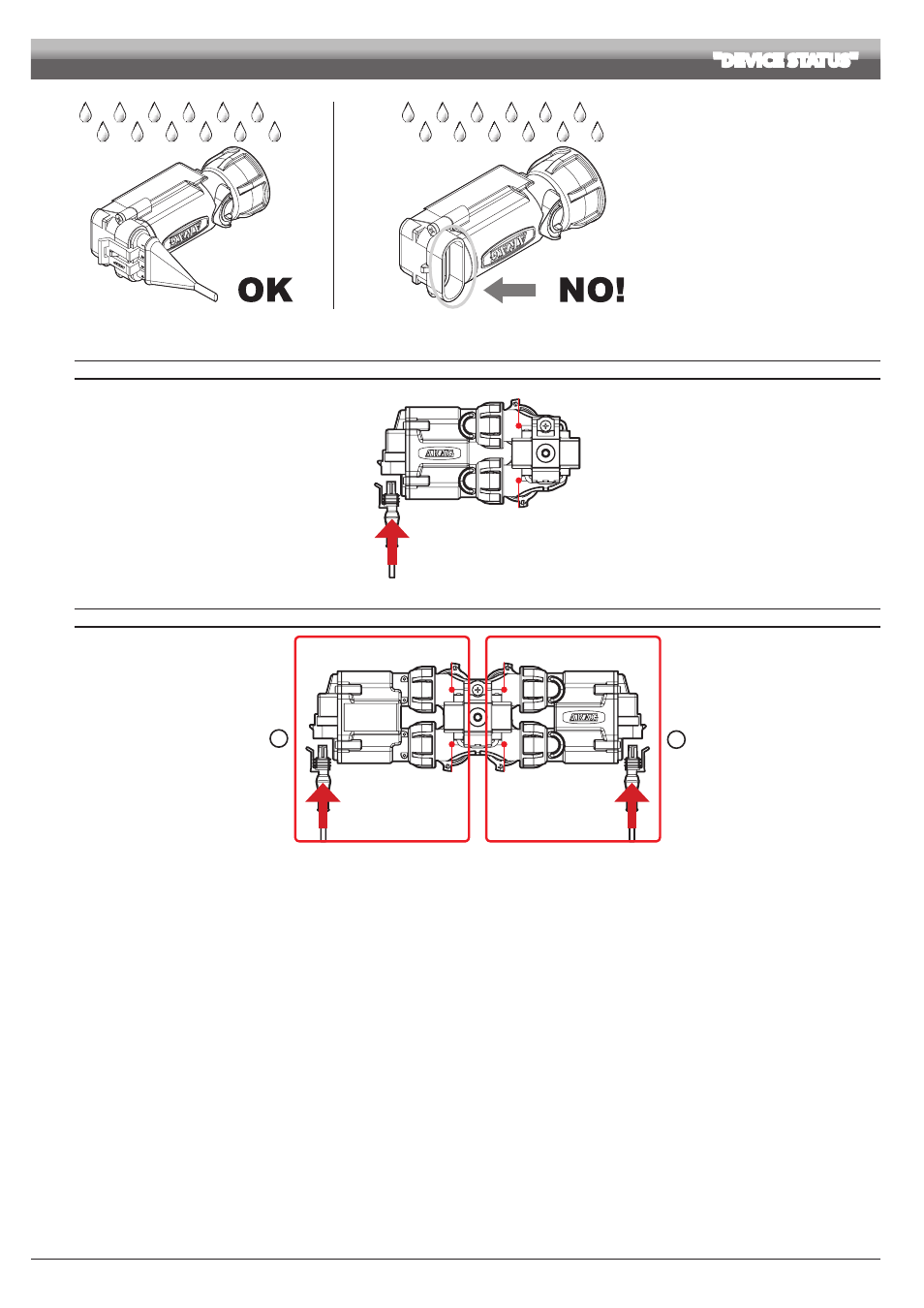
Fig. 215
The products are supplied with valve
installation instructions.
Make sure the device is correctly fitted and
push it until locking it. When the cable is
inserted in the connector, the Seletron is
sealed.
To avoid damaging the internal
components, make sure that when using or
cleaning the system the connectors are not
bare or inserted incorrectly.
CONNECTION SEQUENCE FOR SINGLE AND TWIN SELETRON DEVICES
Connector 1
Nozzle A
Nozzle B
Fig. 216
Connect all Seletron devices in sequence, from left to right until the end of the boom.
CONNECTION SEQUENCE FOR FOURFOLD SELETRON DEVICES
Connector 1
Connector 2
Nozzle A
Nozzle C
Nozzle B
Nozzle D
1
2
Fig. 217
1
Connect in sequence
ONLY SELETRON NOZZLE HOLDERS A AND B, from left to right until the end of the boom (connector 1 in Fig. 217).
2
Start again from the beginning: this time connect
SELETRON NOZZLE HOLDERS C AND D, from left to right until the end of the boom (connector 2).