1 implement, 1 spray spots configuration, Advanced settings "implement – ARAG Bravo 400S Seletron User Manual
Page 24
24
The type of implement displayed depends on the selected basic settings (chap. 9), affecting which items are displayed in Fig. 60.
10.1
Implement
Fig. 60
Advanced implement settings
•
Spray spots configuration
(par. 10.1.1).
•
Boom settings
(par. 10.1.2).
•
Flowmeter
(par. 10.1.3).
•
Filling flowmeter
(par. 10.1.4).
•
Pressure sensor
(par. 10.1.5).
•
Valves
(par. 10.1.6).
•
Nozzles data
(par. 10.1.7).
•
Wheel sensor
(par. 10.1.8).
•
Rev counter
(par. 10.1.9).
•
Tank
(par. 10.1.10).
•
Alarms
(par. 10.1.11).
•
Working parameters
(par. 10.1.12).
•
Device calibration
(par. 10.1.13).
Implement geometry
•
Geometry settings
(par. 10.1.14)
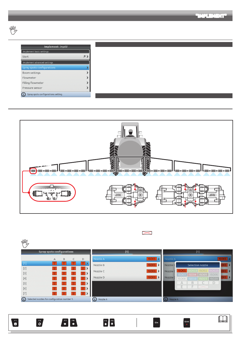
10.1.1 Spray spots configuration
Allows setting 20 different configurations (i.e., 20 nozzle combinations), which can be selected before starting each job.
Each configuration indicates which type of nozzle is installed on the boom spraying points.
NOZZLES
A, B, C, D
Spraying point
Nozzle A
Nozzle C
Nozzle B
Nozzle D
Nozzle A
Nozzle B
Fig. 61
During guided setup (cap. 9), the computer will ask you to indicate which type of Seletron is installed at said spraying points (single, twin or fourfold).
Depending on the selected option the number of nozzles to be programmed in this menu will vary.
- Select the configuration you wish to set up (Fig. 62).
- Select the nozzle you wish to set up (
A
,
B
,
C
or
D
- Select one of the suggested nozzles (Fig. 64): if a nozzle is NOT in use, disable it by selecting
.
- Repeat the setup for each configuration.
The nozzle settings are the same for all spraying points on the boom.
Fig. 62
Fig. 63
Fig. 64
ADVANCED SETTINGS
"IMPLEMENT"
Par.
Exit the function or
data change
Confirm access
or data change
Scroll
(LEFT / RIGHT)
Delete
selected
character
Increase /
decrease
value
Scroll
(UP / DOWN)
Enter
selected
character