9 basic settings, Chap. 9, Basic settings – ARAG Bravo 400S Seletron User Manual
Page 20: Setup "basic settings, Basic implement settings
20
9
BASIC SETTINGS
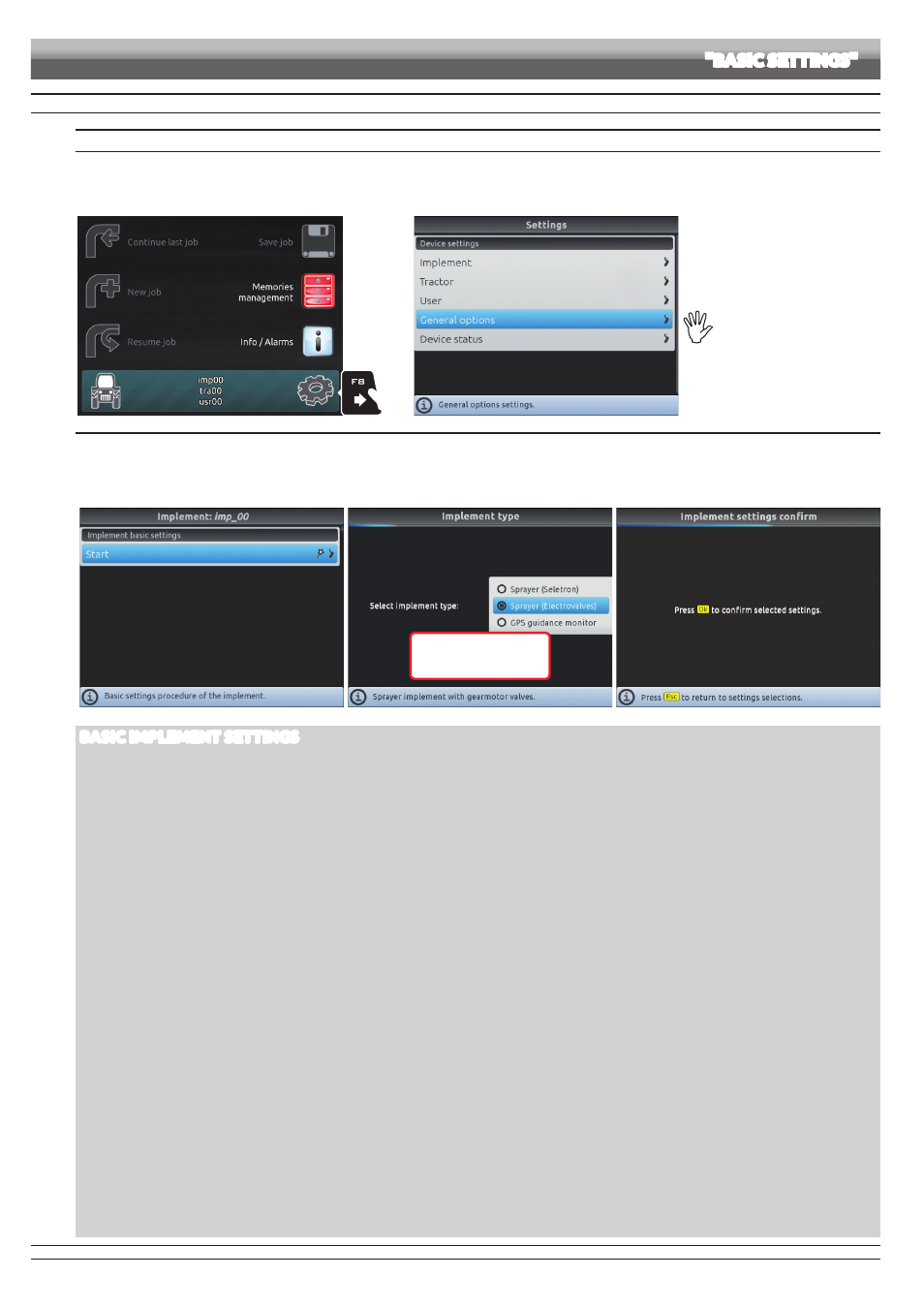
GUIDED SETUP PROCEDURE UPON FIRST SWITCHING ON
1 LANGUAGE SETTING
- In the "Home" screen (Fig. 38) press
F8
to enter the
Settings
menu (Fig. 39).
- Select
General options > Language
and set the language of Bravo 400S.
- Press
ESC
and return to the
Settings
menu. Now select
Implement
to start guided setup procedure as shown in Fig. 40.
1
Fig. 38
Fig. 39
For a correct use of the keys
during setting, refer to par. 7.4.
2 IMPLEMENT
- Upon first switching on, Bravo 400S starts the guided setup procedure for the
Implement
: go through each step selecting the desired options (example in Fig. 41).
OK
: next step
ESC
: previous step.
- When the message in Fig. 42 appears, the implement setup is complete. Press
OK
.
- Press
ESC
and return to the
Settings
menu. Now select
Tractor
to start guided setup procedure as shown in Fig. 43.
Fig. 40
OK
Next step
ESC
Previous step
Fig. 41
Fig. 42
BASIC IMPLEMENT SETTINGS
• IMPLEMENT TYPE
Sprayer (Seletron)
: system with Seletron valves.
Sprayer (Electrovalves)
: system with electric-activated valves - with gearmotor.
GPS guidance monitor
: Bravo 400S is only used as a driving aid and does not control spraying (it is not connected to the RCU).
• IMPLEMENT CONNECTION TYPE
Rear 3-point hitch
Towing hitch
Front 3-point hitch
• MAIN VALVE
Main control valve installed on the control unit:
None
2 ways
(drain valve)
3 ways
(main valve)
• SPRAYING SPOT TYPE
Seletron type: single, twin or fourfold
• FLOWRATE REFERENCE SENSOR
Device used to calculate flowrate:
Flowmeter
Pressure
: measured pressure is used to calculate application rate.
Both
: within the working limits the computer uses the flowmeter, otherwise it uses the pressure sensor, ONLY if properly configured.
• SWITCH PANEL TYPE
Sequential section switches
: switch box with sequential control
5 Section switches (Direct)
: 5-way switch box
7 Section switches (Direct)
: 7-way switch box
• TERMINAL NOZZLES
None
"Buffer zone" nozzles
: it selects, through the switch panel, the nozzle to use according to the "Buffer zone", see par. 12.2.1 "Buffer Zone" function enabled on
• TANK LEVEL SOURCE
Device used to read tank level:
Manual
: no device connected
Filling flowmeter
Tank level sensor
SETUP
"BASIC SETTINGS"
CONTINUES > > >