Introduction – Sierra Video UPC-166 User Manual
Page 25
Introduction
UPC-166 Functional Description
UPC-166 Rear I/O
Modules
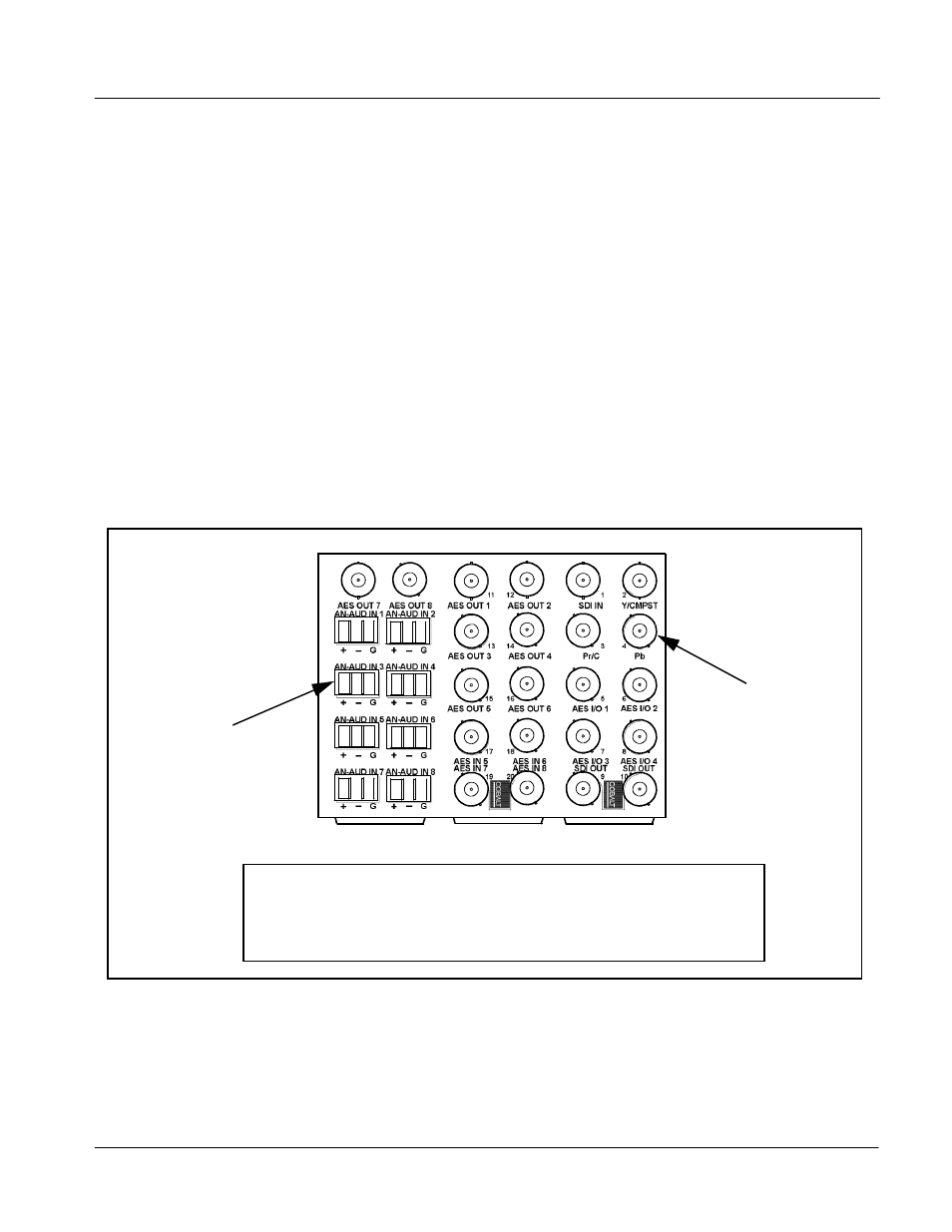
The UPC-166 physically interfaces to system video and audio connections
using a Rear I/O Module. Figure 1-10 shows a typical UPC-166 Rear I/O
Module.
All inputs and outputs shown in the UPC-166 Functional Block Diagram
(Figure 1-1) enter and exit the card via the card edge backplane connector.
The Rear I/O Module breaks out the UPC-166 card edge connections to
industry standard connections that interface with other components and
systems in the signal chain.
In this manner, the particular inputs and outputs required for a particular
application can be accommodated using a Rear I/O Module that suits the
requirements. The required input and outputs are broken out to the industry
standard connectors on the Rear I/O Module; the unused inputs and outputs
remain unterminated and not available for use.
The full assortment of UPC-166 Rear I/O Modules is shown and
described in
UPC-166 Rear I/O Modules (p. 2-6) in Chapter 2, “Installation and
Setup”.
connectors for balanced
Figure 1-10 Typical UPC-166 Rear I/O
Module
1-21
UPC-166-OM
(V4.0)
BNC connectors for coaxial
video and AES audio signals
3-wire Phoenix terminal block
analog audio signals
UPC-166GA.PNG
In this example, an RM-UPC-166-G Rear I/O Module provides a connection interface for
the signal types shown here.
Rear I/O Modules RM-UPC-166-A through RM-UPC-166-F offer other options particularly
suited to various requirements.
• • •
• • •
• • •
• • •
• • •
• • •
• • •
• • •