2 description – Comtech EF Data SDM-2020 User Manual
Page 184

SDM-2020 Satellite Demodulator
Revision 4
SMPTE-310M Data Interface
MN/SDM2020D.IOM
12–2
12.1.2 Description
The SMPTE 310M data interface is a plug-in module that inserts into the rear panel of the
chassis. The data interface provides a physical and electrical connection between the
external terrestrial circuit and the internal circuitry of the unit. By convention, a modem
is Data Communications Equipment (DCE) where transmit data enters the data interface
and receive data exits. The data interface has full-duplex capability but is automatically
configured for simplex-transmit or simplex-receive operation, depending upon whether it
is plugged into a modulator or demodulator chassis.
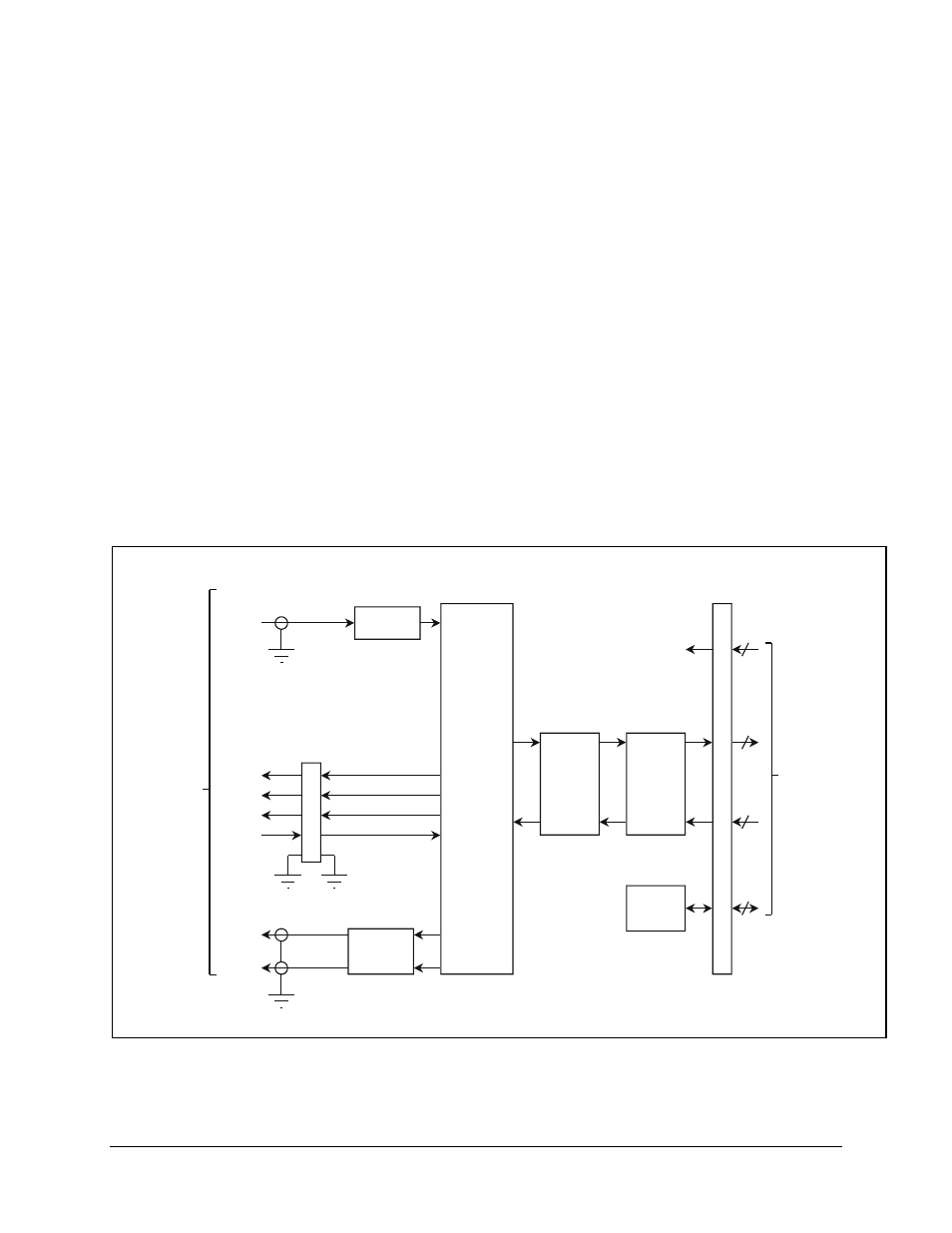
Figure 12-1 shows the SMPTE 310M data interface block diagram. At a functional level,
the data interface has four I/O ports. Transmitted data by the modulator enters the
SMPTE-310M data interface at the TX input as a synchronous serial bit stream, while
data received by a demodulator is sent by the data interface at the RX outputs as a
synchronous serial bit stream. The TX and RX serial data is biphase-mark encoded. The
modem interface is byte-oriented interface with clock, data, and synchronous signals.
Finally, the auxiliary function port provides status outputs for modulator and demodulator
faults as well as input for control and transmission.
Figure 12-2 illustrates the SMPTE 310M module assembly.
SMPTE 310
Recovery
J6
Signal
Processing
Au
xili
ar
y
MF
DF
/CD
J4
J3
SMPTE 310
Generator
Loopback
Level
Translators
M&C
Modulator /
Demodulator
Interface
Terrestrial
Interface
Tx
Data
75 Ohm
BNC-F
Rx
Data
75 Ohm
BNC-F
DC
Power
J5
RTS
96 Pin
DIN
Figure 12-1. SMPTE-310M Interface Block Diagram
