Comtech EF Data SDM-2020 User Manual
Page 156
SDM-2020 Satellite Demodulator
Revision 4
ECL/HSSI Data Interface
MN/SDM2020D.IOM
10–4
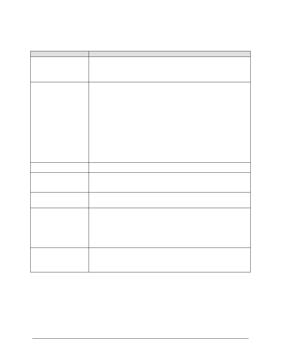
Table 10-3. Terrestrial Transport Protocols
Condition
Description
TX Data Valid Input
For all TX framing modes, the data valid input “DVALID” is ignored. Packet structures
and validity of data are based on the programmed frame format.
For all RX framing modes, the data valid output “DVALID” will operate as defined in
the frame mode definitions.
TX Interface Synchronization
Modes
The TX interface supports two synchronization modes:
Sync Byte Data Correlation Mode - Frame synchronization is correlated from the
packet input data, based on the embedded sync word (47 HEX). In this mode the
“SYNC” input is ignored.
External Sync Mode - Frame synchronization is based on the external “SYNC” input.
In this mode the data which occupies the sync byte data position(s) is over written
with a valid sync word (47 HEX) based on the occurrence of the “SYNC” input timing
by the Modem.
Notes:
The frame synchronization mode is not directly selectable by the user from the front
panel interface.
Synchronization mode is drive from the Modulator configuration interface sync mode
selection programmable from the front panel.
Serial Data Formats
The processing order always starts from the MSB (i.e. “0”) of the sync word-byte (i.e.,
01000111).
187 Byte (no framing) Serial
Format
The 187-byte format contains no framing information. Figure 10-1 shows the general
packet arrangement from the receiver. There is no sync, so the “SYNC” signal is
always logic “0”. Since data is always present, the data valid signal “DVALID” is
always logic “1”. The SYNC and DVALID signals into the transmitter are not utilized
188 Byte Serial Format
The 188-byte serial format consists of 1 sync byte (8 bits, MSB first), followed by 187
payload bytes (1496 bits). Figure 10-2 shows the signal relationships for the 188 byte
serial interface. The DVALID signal into the transmitter is not utilized.
Serial Format
The 204 byte serial format consists of 1 sync byte (8 bits, MSB first), 187 payload
bytes (1496 bits), and 16 dummy bytes (128 bits for Reed-Solomon check-sum).
Typically the 16 dummy bytes reserved for Reed-Solomon coding are set to zero
(logic low), this is a requirement at the receive interface. Figure 10-3 shows the signal
relationships for the 204 byte serial format.
Note: Observe the “DVALID” signal is de-asserted during the last 16 bytes of the
frame. The DVALID signal into the transmitter is not utilized.
204 Byte DBS Serial Format
A special case of the 204 byte format is the Digital Broadcast via Satellite (DBS)
mode. The DBS mode is the same as the general 204 byte format except that the
sync pulse is only asserted during the first bit of the sync byte. Figure 10-4 shows the
signal relationships for the 204 byte DBS serial format. The DVALID signal into the
transmitter is not utilized.