3 receive output connectors, j6/j7, bnc, female – Comtech EF Data SDM-2020 User Manual
Page 150

SDM-2020 Satellite Demodulator
Revision 4
ASI/RS-422Data Interface
MN/SDM2020D.IOM
9–6
Single-ended signals (MF and DF fault signals) are open collector where:
V
oh
=12V max. and V
ol
=0.5V max. @ I
ol
=8 ma.
A pull-up resistor, external to the equipment, is required.
The fault signals, MF and DF, operate as follows: A fault is indicated by an “OFF” (high)
and OK status is indicated by an “ON” (low).
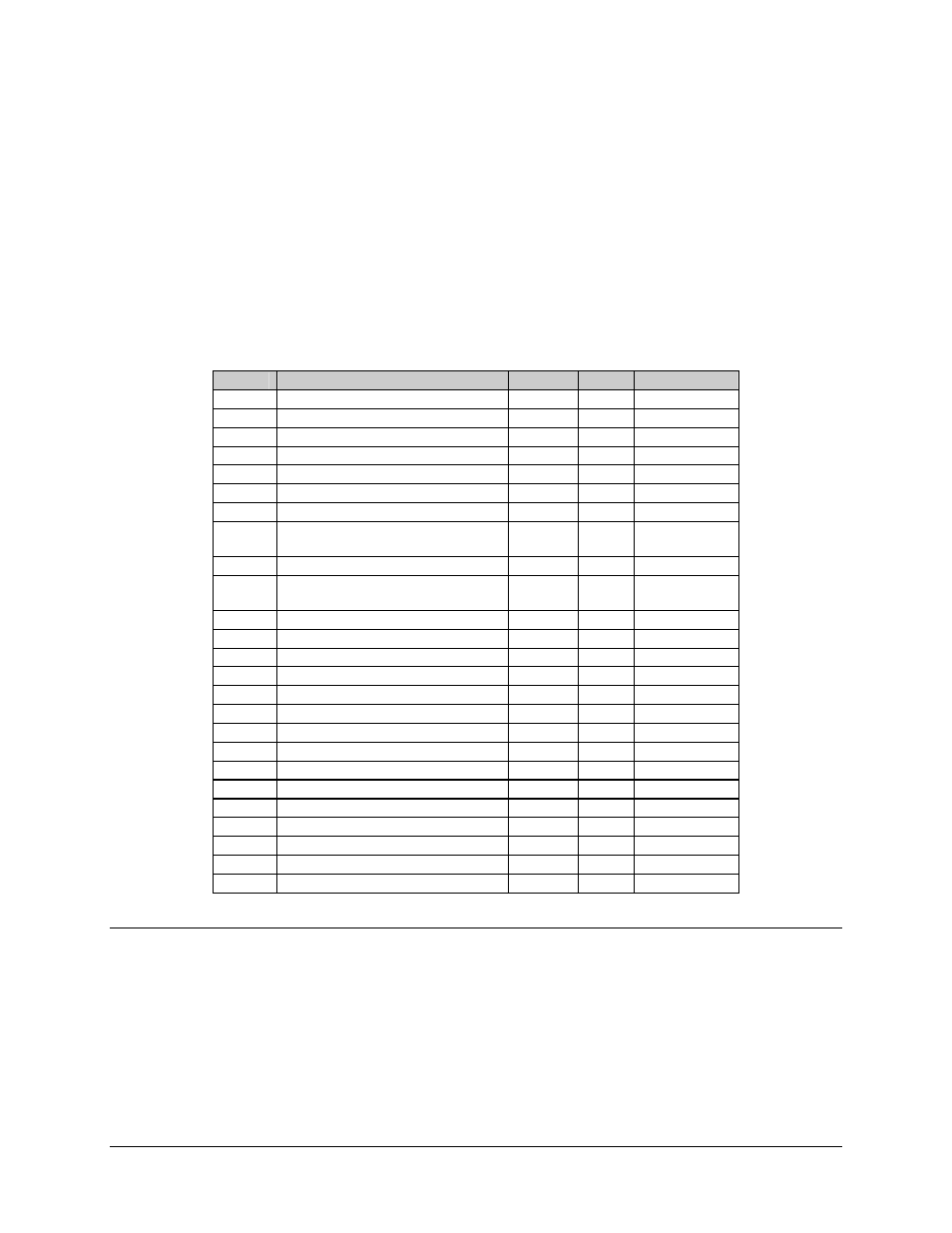
Table 9-2. RS-422 Connector Pinout (Per EIA-530), J5
Pin #
Signal Function
Name
Type
Comment
1 530
Shield
Shield
Mod/Demod
2
Transmit Data (TD-A)
BA-A
I
Modulator
3
Receive Data (RD-A)
BB-A
O
Demodulator
4
Request To Send (RS-A)
CA-A
I
Modulator
5
Clear To Send (CS-A)
CB-A
O
Modulator
6
DCE Ready (DM-A)
CC-A
O
Demodulator
7 Signal
Ground
AB GND
8
Receive Line Signal Detect (RR-
A)
CF-A O Demodulator
9
Receive Timing (RT-B)
DD-B
O
Demodulator
10
Receive Line Signal Detect (RR-
B)
CF-B O Demodulator
11
Terminal Timing (TT-B)
DA-B
I
Modulator
12
Send Timing (ST-B)
DB-B
O
Modulator
13
Clear To Send (CS-B)
CB-B
O
Modulator
14
Transmit Data (TD-B)
BA-B
I
Modulator
15
Send Timing (ST-A)
DB-A
O
Modulator
16
Receive Data (RD-B)
BB-B
O
Demodulator
17
Receive Timing (RT-A)
DD-A
O
Demodulator
18
N/C
19
Request To Send (RS-B)
CA-B
I
Modulator
20 Not
Used
21
Demodulator Fault (DF)
DF
O
Demodulator
22
DCE Ready (DM-B)
CC-B
O
Demodulator
23 Not
Used
24
Terminal Timing (TT-A)
DA-A
I
Modulator
25
Modulator Fault (MF) MF
O
Modulator
9.1.3.3 Receive
Output
Connectors, J6/J7, BNC, Female
Duplicate signals exit both of these connectors on the demodulator to deliver receive data
to the terrestrial interface. J6 and J7 are both active at all times, and no selection is
required.
