3 spod ps 2 ‘j3 | power in’ (dc power main) – Comtech EF Data SPOD PS 1, PS 1.5, and PS 2 C-, X-, or Ku-Band User Manual
Page 41
SPOD C-, X-, or Ku-Band Outdoor Amplifier
MN-SPODPSX
System Connections, Installation and Startup
Revision 1
2–7
2.3.4.3
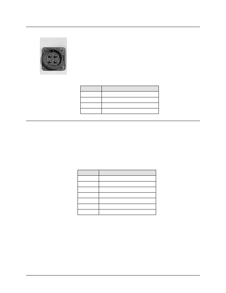
SPOD PS 2 ‘J3 | POWER IN’ (DC Power Main)
The mating connector specification and the pin assignments (Table 2-6)
unique to the SPOD PS 2 DC power interface are as follows:
Mating Connector: CEFD P/N CN/CA3106E2222SB (ITT Cannon CA3106E22-
22SB).
Table 2-6. SPOD PS 2 ‘J3 | POWER IN’ Pin Assignments
Pin
SPOD PS 2 Assignment
A
V+
B
NO CONNECT
C
NO CONNECT
D
V-
2.3.4.4
SPOD PS 2 ‘J3 | POWER IN’ 48VDC Power Main Option
The connector type and mating connector specification and the pin assignments (Table 2-7)
unique to the SPOD PS 2 48 VDC power interface option are as follows:
Unit Connector Type: CEFD P/N CN-0000288 (ITT Cannon CA3102E20-15SB-F80A232).
Supplied Mating Connector: CEFD P/N CN-0000289 (ITT Cannon CA3106E20-15SB-F80A232).
Table 2-7. SPOD PS 2 ‘J3 | POWER IN’ 48VDC Pin Assignments
Pin
SPOD PS 2 Assignment
A
V+
B
V+
C
NO CONNECT
D
NO CONNECT
E
V-
F
V-
G
GROUND (Note 2)
Notes:
1) Use 12 AWG wire to each of the appropriate pins, according to the
individual pin assignments.
2) As an alternative, make the ground connection to the unit's external
ground stud.