4 connector ‘j3 | power in’ (dc power mains), 1 spod ps 1 ‘j3 | power in’ (dc power main), 2 spod ps 1.5 ‘j3 | power in’ (dc power main) – Comtech EF Data SPOD PS 1, PS 1.5, and PS 2 C-, X-, or Ku-Band User Manual
Page 40
SPOD C-, X-, or Ku-Band Outdoor Amplifier
MN-SPODPSX
System Connections, Installation and Startup
Revision 1
2–6
2.3.4
Connector ‘J3 | POWER IN’ (DC Power Mains)
WARNING! FOR SAFETY REASONS, TAKE CARE TO NOTE THAT THE ‘J3’ DC POWER
CONNECTION PIN ASSIGNMENTS FOR EACH SPOD UNIT ARE NOT THE SAME.
FAILURE TO CAREFULLY REVIEW THE INFORMATION PROVIDED IN THE SECTIONS
THAT FOLLOW MAY RESULT IN PRODUCT DAMAGE OR PERSONAL INJURY.
For all SPOD units, the prime power input requirement is 38-72 VDC. The total power required
from the prime power supply depends on the unit used. See Sect. 1.4 Summary of Specifications.
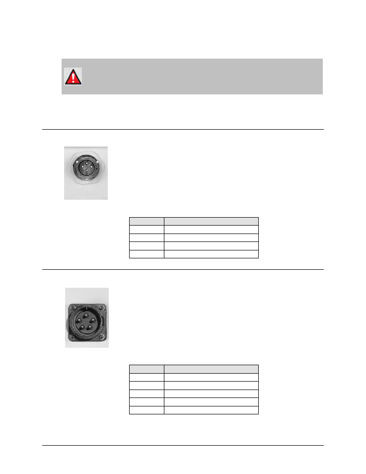
2.3.4.1
SPOD PS 1 ‘J3 | POWER IN’ (DC Power Main)
The mating connector specification and the pin assignments (Table 2-4)
unique to the SPOD PS 1 DC power interface are as follows:
Mating Connector: CEFD P/N CN/STPG04F01 (Glenair IPT06E-12-4-SSR-F7).
Table 2-4. SPOD PS 1 ‘J3 | POWER IN’ Pin Assignments
Pin
SPOD PS 1 Assignment
A
V+
B
GND
C
V-
D
NO CONNECT
2.3.4.2
SPOD PS 1.5 ‘J3 | POWER IN’ (DC Power Main)
The mating connector specification and the pin assignments (Table 2-5)
unique to the SPOD PS 1.5 DC power interface are as follows:
Mating Connector: CEFD P/N CN-0020517 (MS3116E-14-5S(476), Amphenol
PT06E-14-5S(476)).
Table 2-5. SPOD PS 1.5 ‘J3 | POWER IN’ Pin Assignments
Pin
SPOD PS 1.5 Assignment
A
+48V
B
+48V
C
-48V
D
-48V
E
GND