C.2 clean the spod ps 1 heat sinks – Comtech EF Data SPOD PS 1, PS 1.5, and PS 2 C-, X-, or Ku-Band User Manual
Page 182
SPOD C-, X-, or Ku-Band Outdoor Amplifiers
MN-SPODPSX
Appendix C
Revision 1
C–2
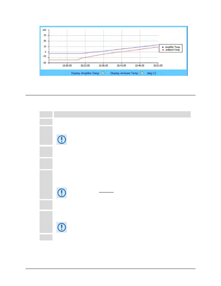
Figure C-2. SPOD Web Server Interface ‘Status |Trending Graphs’ Page
Temperature Graph
C.2
Clean the SPOD PS 1 Heat Sinks
To clean the SPOD PS 1 Heat Sinks, do these steps:
Step
Task
1
Disconnect power from the SPOD.
2
Remove the eight screws – four on either side of the fan shroud – see Figure C-3.
Be sure to use an appropriate screwdriver, such as the one provided
with the SPOD, to avoid damaging the screws.
3
Lift the fan shroud assembly far enough off the chassis to expose the heat sinks and access the fan’s
power supply connection – see Figure C-4.
4
Disconnect the fan power supply. First, depress the connector’s locking mechanism, and then pull
apart the mated components – see Figure C-5.
5
Visually inspect the the exposed SPOD heat sinks, located on the top and either side of the chassis,
for any accumulated debris or blockage that may be obstructing airflow. Use compressed air to clear
and clean the heat sinks as needed – see Figure C-6.
Be sure to blow between the heat sink fins to remove any foreign
object accumulation.
6
Reconnect the fan power supply by pressing the male and female connectors together until the
locking mechanism snaps and locks – see Figure C-7.
7
Re-install the fan shroud onto the chassis – be sure to keep the fan power supply cable clear of the
fan and heat sink surfaces. Then, re-install the eight screws as described in Step 2.
Torque the screws to 11 ±2 inch lbs.
8
Reconnect the power source to the SPOD.