No output register mode – Altera LVDS SERDES Transmitter / Receiver User Manual
Page 48
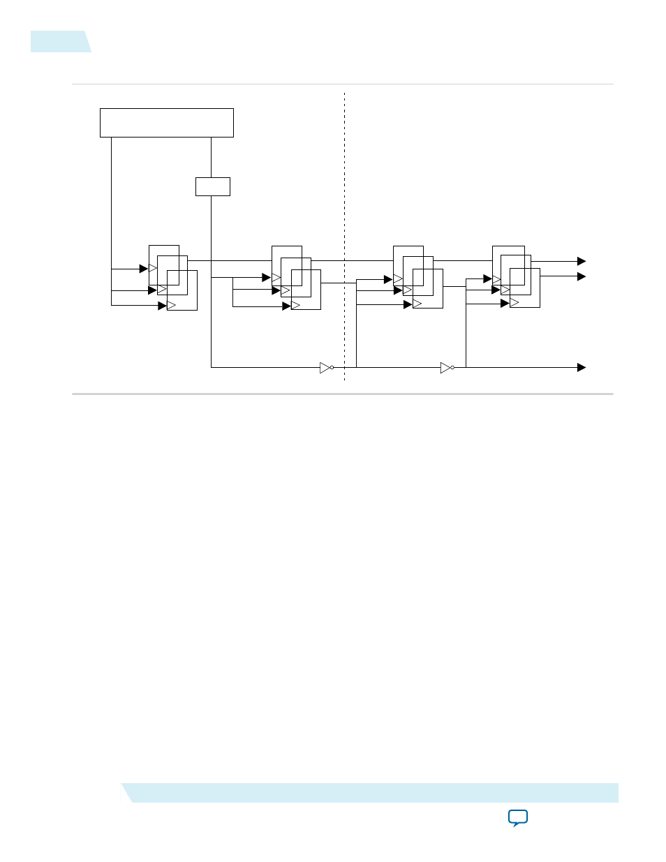
Figure 7: ALTLVDS_RX Block in Standard Mode
DPA
ALTLVDS_RX slow
registers
divfwdclk
Core capture &
sync registers
Core sync
registers
÷
rx_out[]
rx_divfwdclk
ALTLVDS_RX fast
registers
ALTLVDS_RX
Core
Note: For LVDS RX channel operating in soft-CDR mode, Altera recommends you to use
rx_divfwdclk
(instead of any static clock) as the SignalTap capturing clock. Using static clock as the SignalTap
capturing clock leads to bit error during the SignalTap sampling.
No Output Register Mode
The following figure shows the implementation of soft-CDR mode in no-output register mode. In this
mode, you must create the capture registers by the user logic. To ensure even slack for both setup and
hold, you must clock the first capture register stage by the falling edge of the
rx_divfwdclk
clock and
clock the second stage of the registers by the rising edge of the rx_divwdclk clock. The register clocking
method gives the equivalent implementation as the standard mode implementation.
48
No Output Register Mode
UG-MF9504
2014.12.15
Altera Corporation
LVDS SERDES Transmitter/Receiver IP Cores User Guide