Benchmark 1.5ln dual-fuel low nox boiler, Gf-121 – AERCO BMK 1.5 LN Dual Fuel Feb 2013 User Manual
Page 99
CHAPTER 8: TROUBLESHOOTING GUIDE
PR2: 05/09/12 Page
99 of 162
Benchmark 1.5LN Dual-Fuel Low NOx Boiler
Operation and Maintenance Manual
OMM-0041_0C
GF-121
AERCO International, Inc. • 100 Oritani Dr. • Blauvelt, NY 10913 • Ph: 800-526-0288
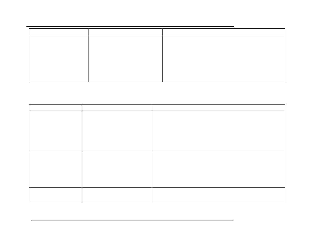
FAULT INDICATION
PROBABLE CAUSES
CORRECTIVE ACTION
STEPPER MOTOR
FAILURE
(continued)
2. Air/Fuel Valve unplugged.
3. Loose wiring connection to the
stepper motor.
4. Defective Air/Fuel Valve stepper
motor.
5. Defective Power Supply Board or
fuse
6. Defective IGST Board
2. Check that the Air/Fuel Valve is connected to the Control Box.
3. .Inspect for loose connections between the Air/Fuel Valve motor
and the wiring harness.
4. Replace stepper motor.
5. Check DS1 & DS2 LEDs on Power Supply Board. If they are not
steady ON, replace Power Supply Board.
6. Check “Heartbeat” LED DS1 and verify it is blinking ON & OFF
every second. If not, replace IGST Board.
8.2 ADDITIONAL FAULTS WITHOUT SPECIFIC FAULT MESSAGES
Refer to Table 8-2 to troubleshoot faults which may occur without a specific fault message being displayed.
TABLE 8-2. BOILER TROUBLESHOOTING WITH NO FAULT MESSAGE DISPLAYED
OBSERVED INCIDENT
PROBABLE CAUSES
CORRECTIVE ACTION
Hard Light-Off
1. Staged Ignition Ball Valve closed.
2. Clogged/damaged Gas Injector
(Figure 8-2).
3. Defective Staged Ignition Solenoid
(Figure 8-2).
4. RSI regulator out of adjustment.
1. Open the 1/4” Ball Valve downstream of the SSOV (Fig. 8-1).
2. Remove and inspect Gas Injector to ensure it is not clogged or
damaged.
3. Close the 2” and the 1/4” Ball Valve downstream of the SSOV (Fig. 8-
1). Start the unit and listen for a “clicking” sound that the Staged
Ignition Solenoid makes during Ignition Trial. If “clicking” sound is not
heard after 2 or 3 attempts, replace the Staged Ignition Solenoid.
4. See Chapter 7, Section 7.4.
Fluctuating Gas Pressure
1. Gas pressure going into unit is
fluctuating.
2. Damping Orifice not installed.
3. RSI Regulator not properly
adjusted.
1. Stabilize gas pressure going into unit. If necessary, troubleshoot
Building Supply Regulator.
2. Check to ensure that the Damping Orifice is installed in the SSOV
Actuator shown in Figure 8-3. (For IRI Gas Trains, the Damping Orifice
is installed in the downstream SSOV Actuator).
3. Refer to Chapter 4, paragraph 4.3 for RSI Regulator Calibration
procedure.
Air/Fuel Valve “hunting” at
the 80% Valve Position
1. IGST and Power Supply Boards in
Control Box are outdated.
1. Check to ensure that the IGST and Power Supply Boards are Rev. E
or higher.