2 setting the unit, Benchmark 1.5ln dual-fuel low nox boiler, Gf-121 – AERCO BMK 1.5 LN Dual Fuel Feb 2013 User Manual
Page 13
CHAPTER 2: INSTALLATION
PR2: 05/09/12 Page
13 of 162
Benchmark 1.5LN Dual-Fuel Low NOx Boiler
Operation and Maintenance Manual
OMM-0041_0C
GF-121
AERCO International, Inc. • 100 Oritani Dr. • Blauvelt, NY 10913 • Ph: 800-526-0288
FOR MASSACHUSSETTS ONLY:
For Massachusetts installations, the boiler must be installed by a
plumber or gas fitter who is licensed within the Commonwealth of
Massachusetts. In addition, the installation must comply with all
requirements specified in Chapter 1 (Safety Precautions), pages
1-2 & 1-3.
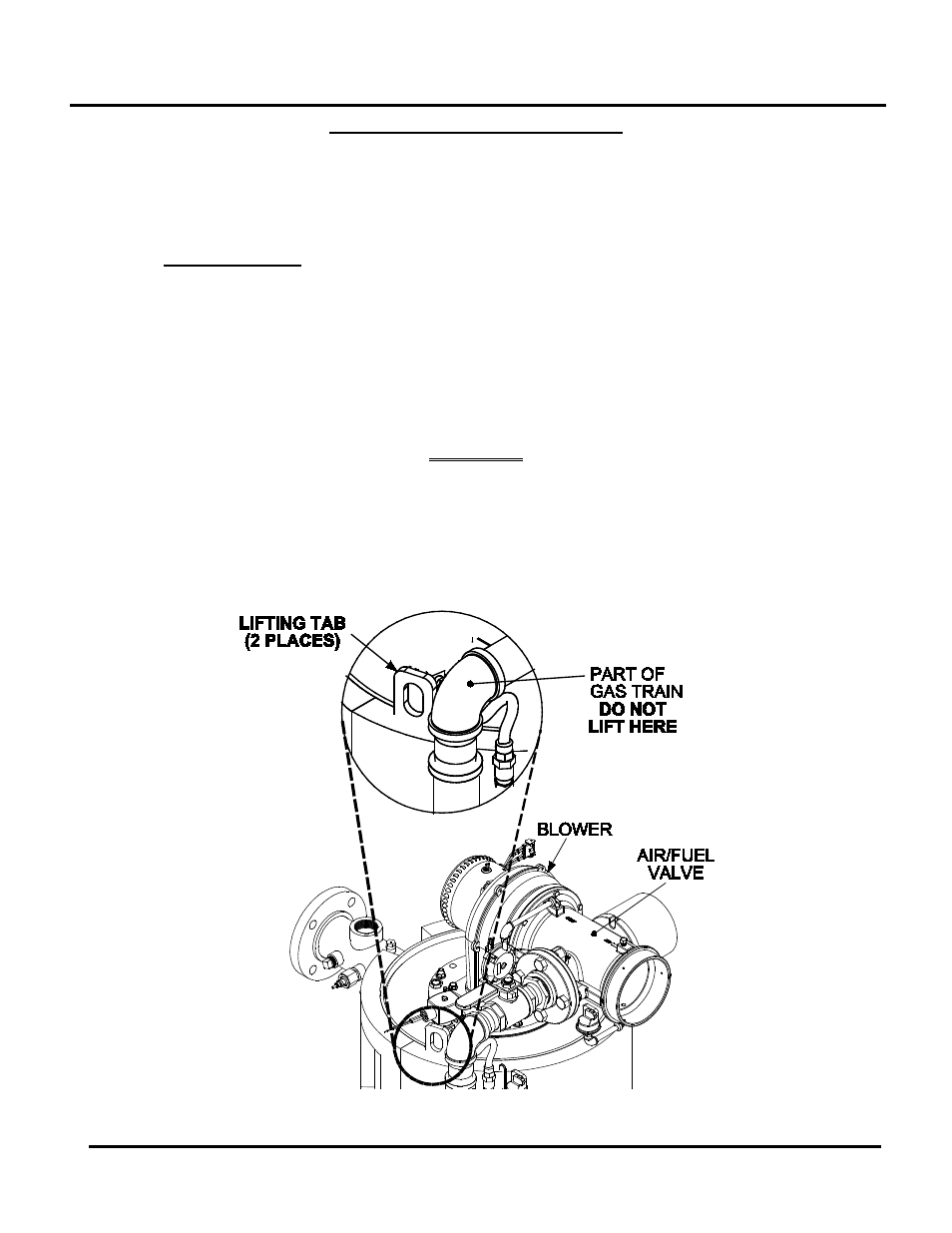
Setting the Unit
2.4.2
The unit must be installed on a 4 inch to 6 inch housekeeping pad to ensure proper condensate
drainage. If anchoring the unit, refer to the dimensional drawings in Appendix F for anchor
locations. Two lifting tabs are provided at the top of the heat exchanger. Figure 2-2 shows the
location of the tab on the top-left side. The second tab is located on the top-right side of the heat
exchanger. USE THESE TWO TABS TO LIFT AND MOVE THE UNIT. Remove the top panel
from the unit to provide access to the lifting tabs. Remove the four (4) lag screws securing the
unit to the shipping skid. Lift the unit off the shipping skid and position it on the 4 inch to 6 inch
housekeeping concrete pad (required) in the desired location.
WARNING
WHEN LIFTING OR MOVING THE BOILER:
•
DO NOT MANIPULATE THE BOILER USING THE GAS
TRAIN OR BLOWER
•
WHEN USING THE LIFTING TABS, ENSURE THERE IS
NO LOAD PLACED ON THE GAS TRAIN OR BLOWER
Figure 2-2: Partial Top View Showing Lifting Tab Location