Benchmark 1.5ln dual-fuel low nox boiler, Gf-121 – AERCO BMK 1.5 LN Dual Fuel Feb 2013 User Manual
Page 85
CHAPTER 7: MAINTENANCE
PR2: 05/09/12 Page
85 of 162
Benchmark 1.5LN Dual-Fuel Low NOx Boiler
Operation and Maintenance Manual
OMM-0041_0C
GF-121
AERCO International, Inc. • 100 Oritani Dr. • Blauvelt, NY 10913 • Ph: 800-526-0288
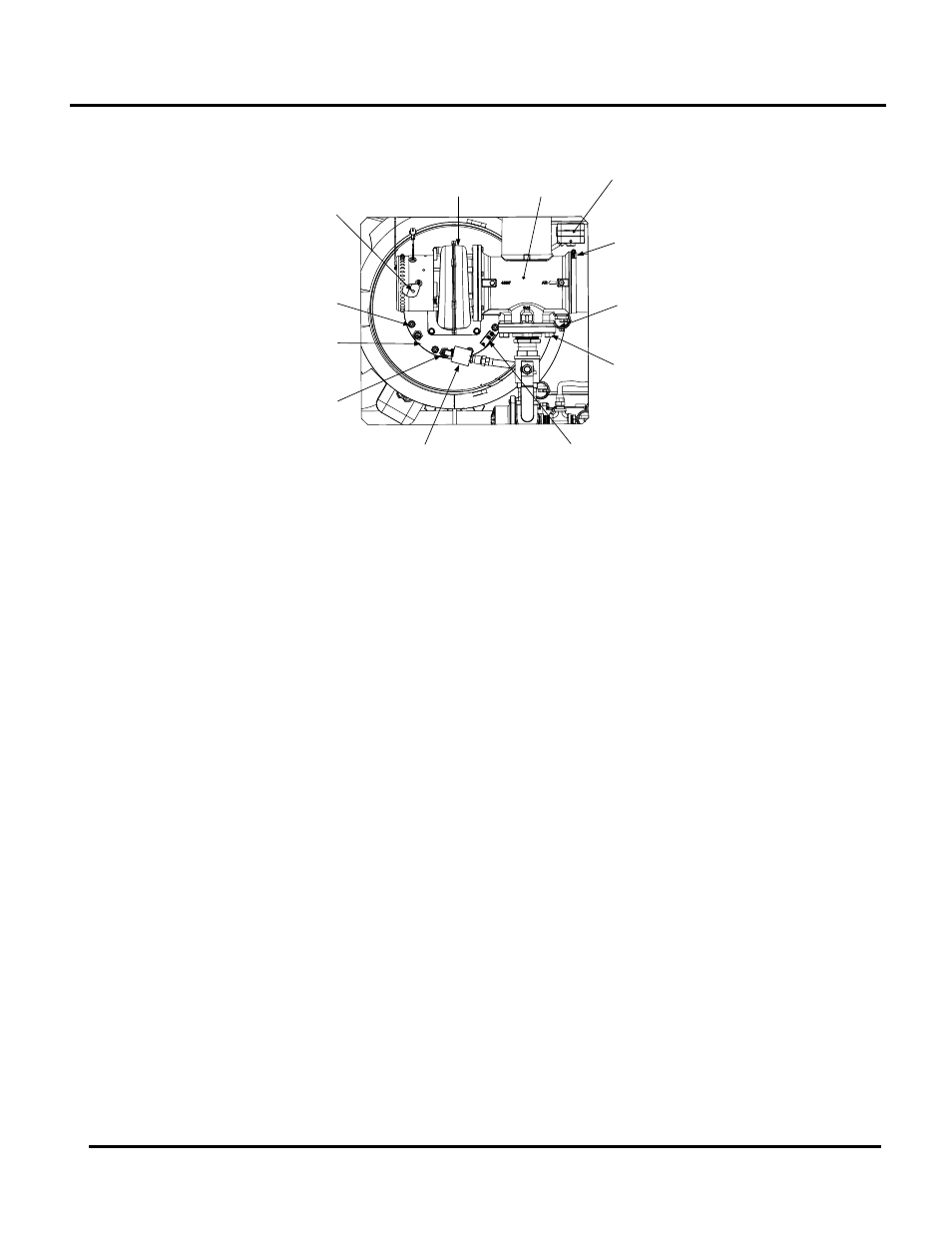
3. Disconnect the lead wire from the flame detector installed on the burner plate. See Figure
7-4.
BLOWER
PROOF
SWITCH
BURNER
PLATE
BLOWER
IGNITER-
INJECTOR
HOSE
CLAMP
FLAME
DETECTOR
STAGED
IGNITION
ASSEMBLY
3/8-16
HEX NUTS
(8)
1/2" BOLTS
& NUTS (4)
AIR/FUEL
VALVE
BLOCKED
INLET
SWITCH
10-32 x 1 /2" LG
GROUNDING
SCREW
Figure 7-4: Burner Assembly Mounting Details
4. Remove the two (2) screws securing the flame detector to the plate. The flame detector is
secured to the burner plate with one (1) #10-32 screw and one (1) #8-32 screw.
5. Remove the flame detector and gasket from the burner plate.
6. Disconnect the cable from the igniter-injector.
7. Using a 7/16” open-end wrench, disconnect the compression nut securing the gas injector
tube of the igniter-injector to the elbow of the staged ignition assembly (see Figure 7-2).
Disconnect the staged ignition assembly from the igniter-injector.
8. Next, loosen and remove the igniter-injector from the burner plate using a 1" open-end
wrench.
9. Disconnect the unit wiring harness connectors from the air/fuel valve and blower motor.
10. Disconnect the wire leads connected to the blower proof switch and blocked inlet switch
(Figures 7-4 & 7-5).
11. Remove the 10-32 x 1/2" long. grounding screw from the burner plate (Figures 7-4 and 7-
5).
12. Disconnect the gas train from the air/fuel valve by removing the four (4) 1/2” bolts and nuts
(Figure 7-4).
13. Disconnect the flex hose from the air/fuel valve by loosening the hose clamp.
14. Remove the four (4) 5/16-18 hex head screws securing the blower to the burner plate
(Figure 7-5).
15. Remove the blower and air/fuel valve from the burner plate by lifting straight up. Also,
remove the blower gasket.
16. Remove the eight (8) 3/8-16 nuts from the burner flange (Figure 7-4) using a 9/16” wrench.