1 constant setpoint mode, 2 indoor/outdoor reset mode, 3 boiler management system mode – AERCO BMK 1.5 LN Dual Fuel Feb 2013 User Manual
Page 20: Benchmark 1.5ln dual-fuel low nox boiler, Gf-121
CHAPTER 2: INSTALLATION
Page
20 of 162 PR2: 05/09/12
Benchmark 1.5LN Dual-Fuel Low NOx Boiler
Operation and Maintenance Manual
OMM-0041_0C
GF-121
AERCO International, Inc. • 100 Oritani Dr. • Blauvelt, NY 10913 • Ph: 800-526-0288
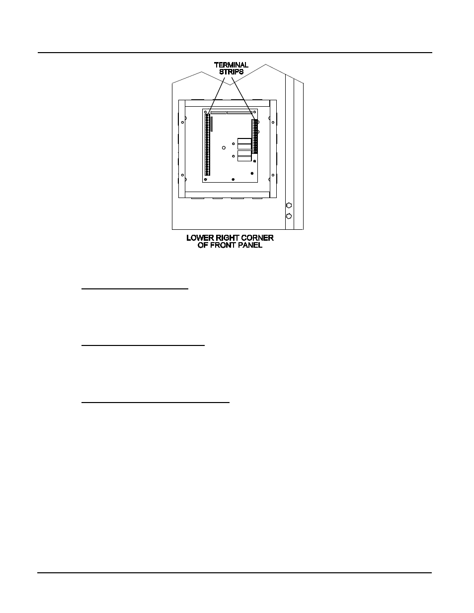
Figure 2-9: Input/Output (I/O) Box Location
Constant Setpoint Mode
2.9.1
The Constant Setpoint Mode is used when it is desired to have a fixed setpoint that does not
deviate. No wiring connections, other than AC electrical power connections, are required for
this mode. However, if desired, fault monitoring or enable/disable interlock wiring can be
utilized (see paragraphs 2.9.9.1 and 2.9.10).
Indoor/Outdoor Reset Mode
2.9.2
This mode of operation increases supply water temperature as outdoor temperatures decrease.
An outside air temperature sensor (AERCO Part No. 122790) is required. The sensor MUST
BE wired to the I/O Box wiring terminals (see Figure 2-10). Refer to paragraph 2.10.1 for
additional information on outside air temperature sensor installation.
Boiler Management System Mode
2.9.3
NOTE
BMS Model 168 can utilize either pulse width modulation (PWM)
or RS485 Modbus signaling to the Boiler. BMS II Model 5R5-384
and the AERCO Control System (ACS) can utilize only RS485
signaling to the Boiler.
When using an AERCO BMS, BMS II, or ACS (AERCO Control System), the field wiring is
connected between the BMS/BMS II/ACS Panel and each Boiler’s I/O Box terminal strip (Figure
2-10). Twisted shielded pair wire from 18 to 22 AWG must be utilized for the connections. The
BMS Mode can utilize either pulse width modulation (PWM) signaling, or RS485 Modbus
signaling. For PWM signaling, connections are made from the AERCO Boiler Management
System to the B.M.S. (PWM) IN terminals on the I/O Box terminal strip. For RS485 Modus
signaling, connections are made from the BMS/BMS II/ACS to the RS485 COMM terminals on
the I/O Box terminal strip. Polarity must be maintained and the shield must be connected only at
the AERCO BMS/BMS II/ACS. The boiler end of the shield must be left floating.
For additional instructions, refer to Chapter 5, paragraph 5.6 in this manual. Also, refer to GF-