2 igniter-injector, Benchmark 1.5ln dual-fuel low nox boiler, Gf-121 – AERCO BMK 1.5 LN Dual Fuel Feb 2013 User Manual
Page 79
CHAPTER 7: MAINTENANCE
PR2: 05/09/12 Page
79 of 162
Benchmark 1.5LN Dual-Fuel Low NOx Boiler
Operation and Maintenance Manual
OMM-0041_0C
GF-121
AERCO International, Inc. • 100 Oritani Dr. • Blauvelt, NY 10913 • Ph: 800-526-0288
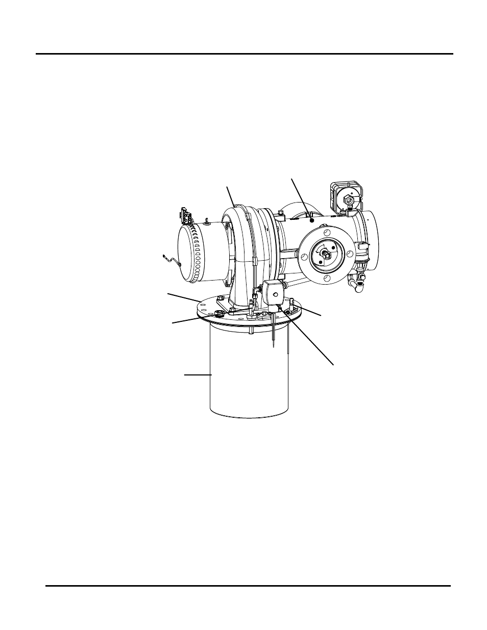
7.2 IGNITER-INJECTOR
The igniter-injector (part no. 58023) is located on the burner plate at the top of the boiler. In
addition to providing the ignition spark required to light the burner, the igniter-injector also
contains a gas injector tube which connects to the staged ignition assembly. Figure 7-1 shows
the complete burner assembly removed from the boiler and indicates the location of the igniter-
injector flame detector and other related components.
The igniter-injector may be hot, therefore, care should be exercised to avoid burns. It is easier to
remove the igniter-injector from the unit after the unit has cooled to room temperature.
AIR/FUEL
VALVE
STAGED
IGNITION
ASSEMBLY
FLAME
DETECTOR
IGNITOR-
INJECTOR
BLOWER
BURNER
PLATE
BURNER
Figure 7-1: Benchmark 1.5LN Burner Assembly (Shown Removed from Boiler)
To inspect/replace the Igniter:
1. Set the
ON/OFF switch on the control panel, to the OFF position. Disconnect AC power
from the unit
2. Remove the side and top panels from the unit.
3. Disconnect the cable from the igniter-injector (Figure 7-1).
4. Refer to the partial exploded view in Figure 7-2. Using a 7/16” open-end wrench,
disconnect the compression nut securing the gas injector tube of the igniter-injector to the
elbow of the staged ignition assembly. Disconnect the staged ignition assembly from the
igniter-injector.