5 supply and return piping, 6 condensate drain, Benchmark 1.5ln dual-fuel low nox boiler – AERCO BMK 1.5 LN Dual Fuel Feb 2013 User Manual
Page 14: Gf-121
CHAPTER 2: INSTALLATION
Page
14 of 162 PR2: 05/09/12
Benchmark 1.5LN Dual-Fuel Low NOx Boiler
Operation and Maintenance Manual
OMM-0041_0C
GF-121
AERCO International, Inc. • 100 Oritani Dr. • Blauvelt, NY 10913 • Ph: 800-526-0288
In multiple unit installations, it is important to plan the position of each unit in advance. Sufficient
space for piping connections and future service/maintenance requirements must also be taken
into consideration. All piping must include ample provisions for expansion
.
If installing a Combination Control Panel (CCP) system, it is important to identify the
Combination Mode Boilers in advance and place them in the proper physical location. Refer to
Chapter 5 for information on Combination Mode Boilers.
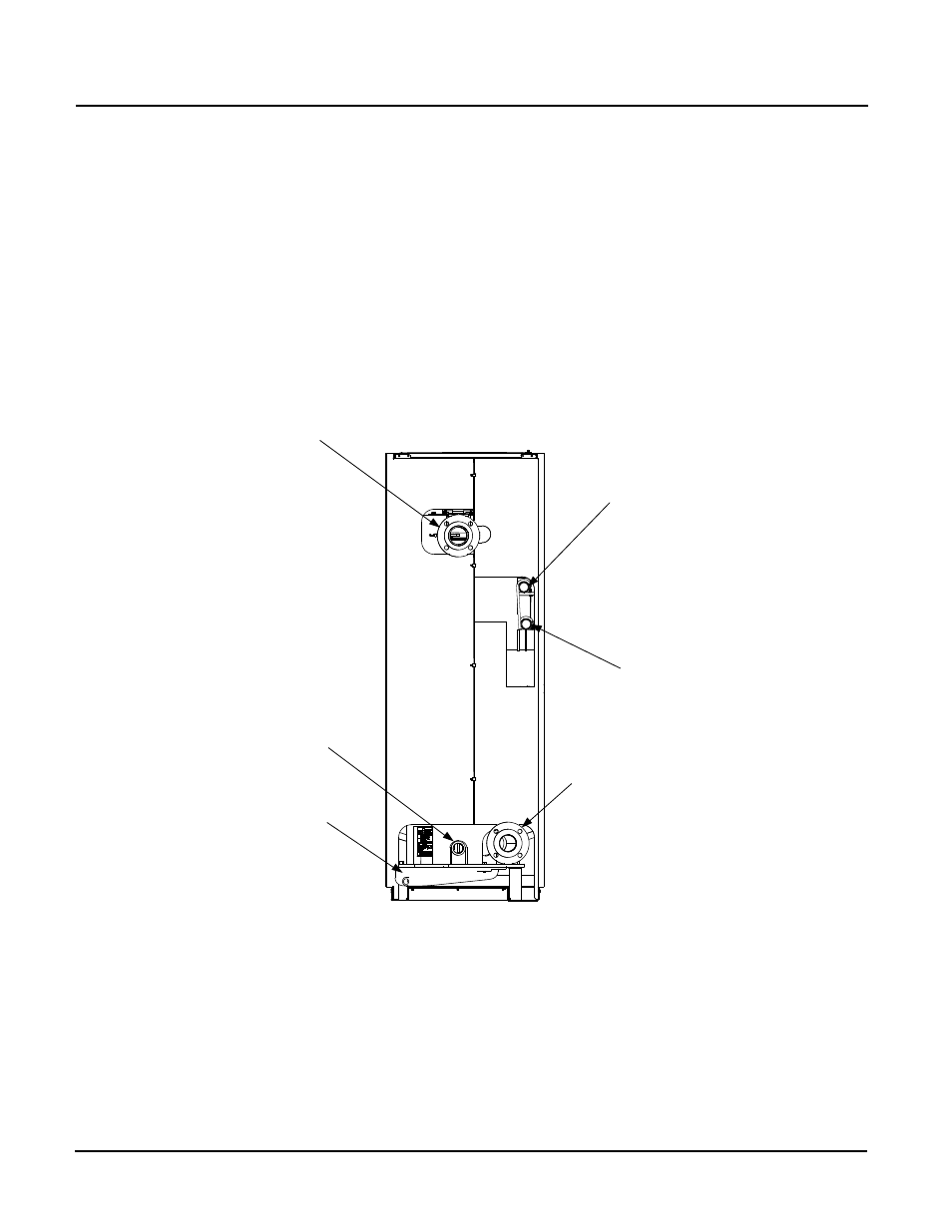
2.5 SUPPLY AND RETURN PIPING
The Benchmark 1.5 Boiler utilizes 3” 150# flanges for the water system supply and return piping
connections. The physical location of the supply and return piping connections are on the rear of
the unit as shown in Figure 2-3. Refer to Appendix F, Drawing AP-A-832 for additional
dimensional data.
BOILER SUPPLY
3" – 150# FLANGED
CONNECTION
BOILER RETURN
3" – 150# FLANGED
CONNECTION
1-1/2”
NATURAL
GAS INLET
CONNECTION
SHELL DRAIN
VALVE
EXHAUST
MANIFOLD
REAR VIEW
1-1/2”
PROPANE INLET
CONNECTION
Figure 2-3: Supply and Return Locations
2.6 CONDENSATE DRAIN
The Benchmark 1.5 Boiler is designed to condense water vapor from the flue products.
Therefore, the installation must have provisions for suitable condensate drainage or collection.
The condensate drain pipe located on the exhaust manifold (Figure 2-4) must be connected to a
condensate trap which is packed separately within the unit’s shipping container.
The procedure to install and connect the condensate drain is provided in paragraph 2.6.1.