6 signal and status outputs o3, o4, o5, Signal and status outputs o3, o4, o5 – Pilz PNOZ s50 C User Manual
Page 21
Function description
Operating Manual PNOZ s50
1002194EN02
21
Please note the fixed allocation of test pulses to the following inputs:
}
T0 pulses the feedback loop Y1
}
T1 pulses the feedback loop Y2
The test pulse outputs T0/T1 are switched on (24 V) in
}
"RUN" operating status.
}
"I/O Fault" operating status (fault on inputs and outputs).
The test pulse outputs T0/T1 are switched off (0 V) in
}
"Fault" operating status (internal fault).
The test pulses can be switched on and off via the display.
}
The default setting is for test pulses to be switched on.
}
Test pulses will not be active in the event of a fault (I/O Fault and Fault).
NOTICE
The test pulses can only be activated simultaneously for both feedback
loops Y1 and Y2.
4.2.6
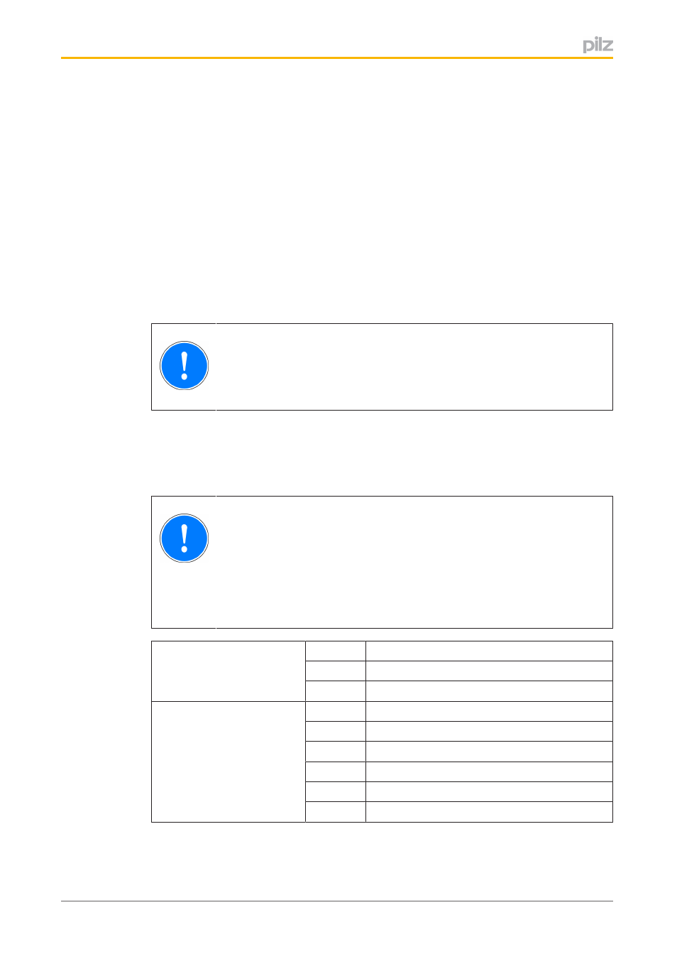
Signal and status outputs O3, O4, O5
Singlepole failsafe semiconductor outputs signal the operating status of the load and indic
ate a fault.
NOTICE
The fault signal output O3 must be evaluated together with status outputs
O4 (if O1+/O1 is used) and O5 (if O2+/O2 is used), if this is demanded by
the plant/machine's safety requirements. Processing of these signals is
used to check the feasibility of the signal states. Evaluation of these signals
must be suitable to achieve a safe condition for the application.
Fault signal output
O3
1
No fault, LED "I/O Fault" and "Fault" is off
0
Fault, LED "I/O Fault" or "Fault" is lit
Status outputs
They signal the status of the
load only after the ventilation
or application time has
elapsed.
O4
1
Load at O1+/O1 ventilated
0
Load at O1+/O1 applied
O5
1
Load at O2+/O2 ventilated
0
Load at O2+/O2 applied