Pilz PNOZ s50 C User Manual
Page 16
Function description
Operating Manual PNOZ s50
1002194EN02
16
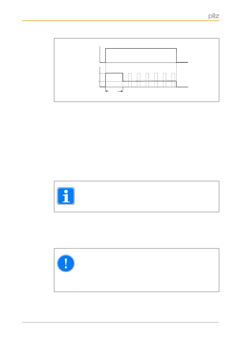
tover
U
B1B2
U
Avg
Y10, Y11
Y20, Y21
01+, 02+
t
t
ton
toff
Fig.: Switching the power circuits on and off
Legend:
}
Y10, Y11, Y20, Y21: Safe inputs to switch the outputs O1+, O2+
}
O1+, O2+: Safe outputs, power circuit 1 and 2
}
U
B1B2
: Supply voltage of power circuits
}
t
on
: Switch on power circuit
}
t
over
: Configured overexcitation time
}
t
off
: Switch off power circuit
}
U
Avg
: Configured reduced voltage (arithmetic mean of the voltage at the outputs once
the overexcitation time has elapsed)
Inputs Y10, Y11 (or Y20, Y21) can be activated via singlepole or dualpole safe outputs.
INFORMATION
Details of the wiring can be found in the chapter entitled "Commissioning",
under "Wiring".
4.2.2
Switching the power circuits on and off (slow shutdown S35, S36)
If the switching times are not critical, the loads at the power circuits can also be shut down
slowly. A connected brake is permitted to have longer application times, for example. The
brake switches with lower noise and is lower wearing.
NOTICE
The power circuit's slow shutdown is not safetyrelated. It may only be used
when permitted by the hazard analysis.
To shut down the inductive load safely, the fast shutdown must be activated
after the slow shutdown. That way the brake has a dualpole shutdown.
A 1/0 pulse edge at one of the slow shutdown inputs (S35 or S36) switches off the corres
ponding power circuit (O1+, O2+) in singlepole mode. A flywheel diode means that the cur
rent only dissipates the magnetic field slowly.