Probe, Line – ETS-Lindgren FM5004 Field Monitor (Archived) User Manual
Page 38
4-PROBE
When selected, the display is divided into four sections, one for each channel.
The reading from each probe is displayed in these sections. If the display is
disabled for a given channel, that section of the display will be empty.
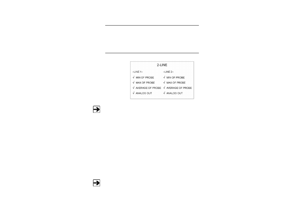
2-LINE
Allows you to
view two
readings on the
display at
one time.
Only one selection at a time may be made from the Line 1 column and
Line 2 column.
The display is divided into two sections, line 1 on top, and line 2 on bottom. The
minimum, maximum, or average of the display-enabled probes appear on each
line, and the reading is sent to the analog output system; see Analog Out Setup
on page 42 for information on setting up the analog output system. Different
channels may be selected for routing to the analog output and display systems,
displaying readings from different probes on each line.
For example, you may display the maximum reading from channel 1 and
channel 2 on line 1, and the maximum of the readings from channel 3 and
channel 4 on line 2. Selecting channel 1 and channel 2 for the display system
and channel 3 and channel 4 for the analog output system will achieve this
set up.
Unless indicated, calculations for the following readings are based on
the number of previous samples, which is determined from the display
update rate. See Display Update Rate on page 41 for information on
setting the display update rate.
38 |
Menu System
Archived 10/19/10