Channel mode indicators – ETS-Lindgren FM5004 Field Monitor (Archived) User Manual
Page 28
When a channel select switch is pressed, the FM5004 establishes
communication with the probe. During this process the base mode (Disp or Out)
LED for that channel will flash. When the connection is established, the LED
lights continuously. If the FM5004 fails to make connection with the probe, the
LED will go dark.
C
HANNEL
M
ODE
I
NDICATORS
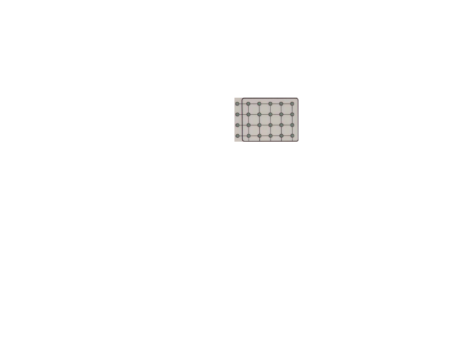
These 24 LEDs form a matrix
that signify the current
channel and base mode
selections. Following are
examples that illustrate the
correspondence between the
LEDs and the base mode
selections.
Example 1–Single Probe Configuration
1.
Press channel select switch Ch-1 to select the probe attached to
channel 1.
2.
Press base mode switches X ,Y, and Z to provide isotropic response.
3.
Press Disp to display the numeric value of the vectorially-combined
axis values.
4.
All LEDs in the top row of the matrix are illuminated, except for the
second from the left.
All other LEDs are dark.
Example 2–Dual Probe Configuration
1.
Press channel select switch Ch-1 to select the probe attached to
channel 1.
2.
Press Ch-2 to select the probe attached to channel 2.
3.
Press base mode switches X and Y to gather the data from only those
two axes.
4.
Press Out to provide the vectorially-combined value of X and Y
reading as an analog output.
28 |
Front Panel Controls and Indicators
Archived 10/19/10