Figure 38: physical assignment of serdes lanes – Achronix Speedster22i SerDes User Manual
Page 84
•
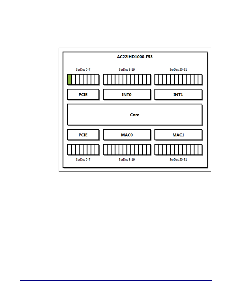
SerDes lanes on the chip are divided into physical groups of 8 lanes (0-7), 12 lanes (8-
19) and 12 lanes (20-31) on the North and South sides of the chip, as seen in Figure 38
– Physical assignment of SerDes Lanes below.
Figure 38: Physical assignment of SerDes Lanes
•
Channel bonding of multiple lanes is limited to fit within the boundaries of each
group. For example, a bonded group of 10 SerDes lanes cannot be placed on lanes 0-
9, since that overlaps the boundary of the physical group of lanes 0-7.
•
On both the North and South sides of the chip, there are additional restrictions on
lanes 20-31 if you instantiate multiple non-bonded serdes lanes. You cannot place
the non-bonded SerDes lanes adjacent to each other. Due to clock muxing
limitations, you must place each non-bonded lane on every other (even numbered)
lane. Figure 39 – SerDes Placement Guidelines below shows available lanes in white,
and illegal/unavailable lanes in gray for a multi-lane non-bonded interface. Note that
if you use channel bonding, you may place your multi-lane bonded interface on any
of the lanes 20-31.
84
UG028, July 1, 2014