Connectors, Installation, Connectors -3 – ClearOne DigiLinX User Manual
Page 82: Installation -3
DoorLinX
11-3
All specifications subject to change without notification. All rights reserved. Copyright © 2008 NetStreams
Main +1 512.977-9393 / fax +1 512.977.9398 / Toll Free Technical Support +1 866-353-3496
3600 W. Parmer Lane, Suite 100; Austin, TX 7872
Connectors
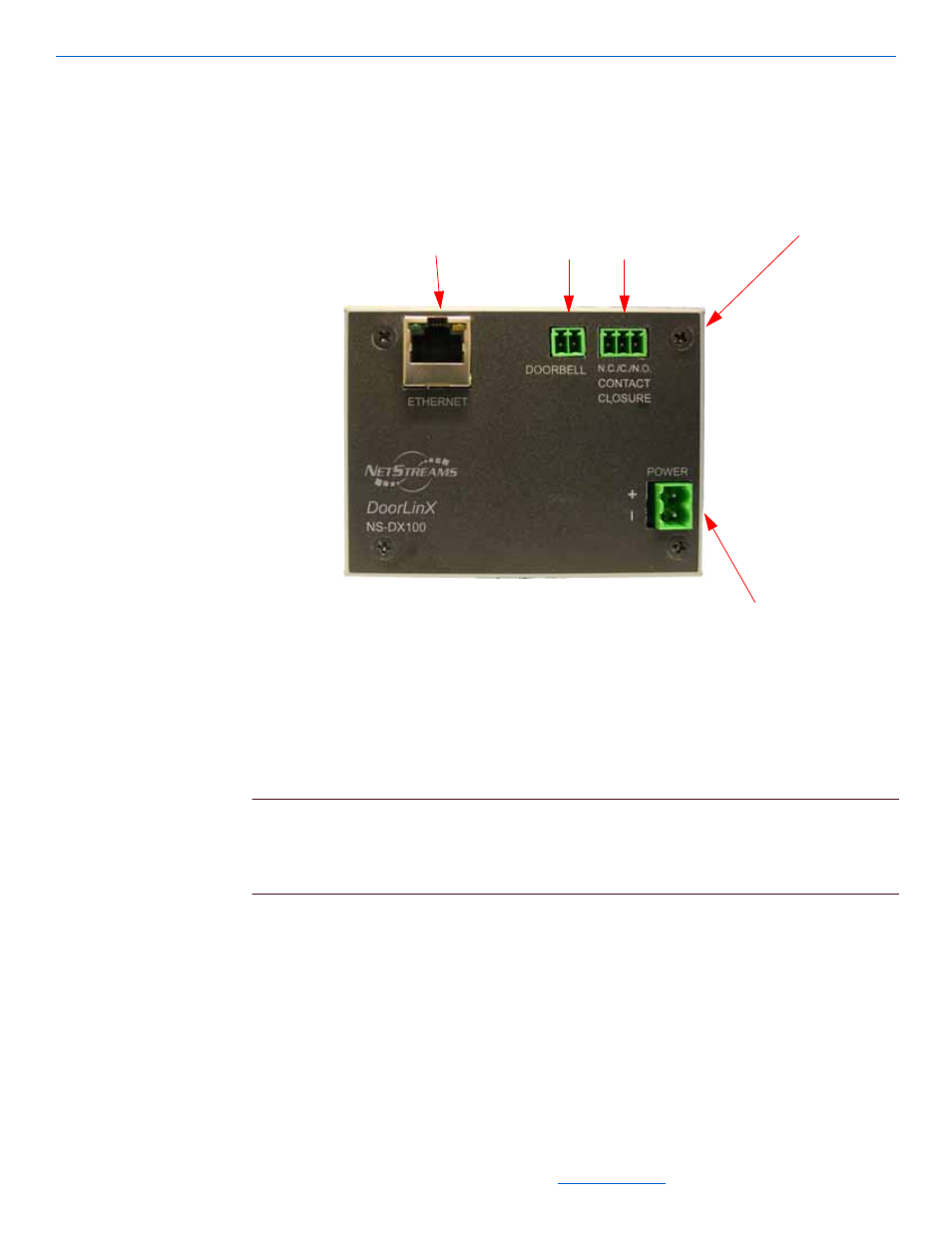
Figure 11-2 shows the connections on the DX100.
Figure 11-2
DoorLinX connections
The DoorLinX electronics package contains the connectors needed to connect the
DoorLinX into the DigiLinX network. Terminations for the DoorLinX include:
Ethernet: RJ45 connectors, 568a termination standard
power: 2-pin Phoenix connector (provided)
CAUTION!
The contact closure is rated to a maximum of 1A. Do not attempt to drive a
door strike directly from the contact closure. Connect another relay to the
DoorLinX contact closure and use the DoorLinX to trip this relay to run the
high-current door strike.
doorbell: 2-pin Phoenix connector (provided)
contact closure: 3-pin Phoenix connector (provided).
Installation
To install DoorLinX, you must install the mounting bracket and the doorbell mounting
plate, connect the cables, and mount the electronics package, faceplate, and doorbell.
Ethernet (Network)
Connection
2-pin 3.5mm
Phoenix
connector
3-pin 3.5mm
Phoenix connector
2-pin 5mm Phoenix
connector
Normally
Closed,
Closed,
Normally
Open