2 typical setup and startup sequence, 3 startup and troubleshooting – Banner PresencePLUS Pro COLOR—PROII Camera User Manual
Page 25
3.2 Typical Setup and Startup Sequence
The following subsections proceed through a typical Sensor setup and startup sequence
1. Connect and power up the hardware.
2. Start up the software.
3. Set up hardware parameters.
4. Build and run an inspection.
3.3 Startup and Troubleshooting
The following explains how to verify connections and start the PresencePLUS software.
1. Check the following essential components.
• Camera
• C-mount lens
• Camera cable
• Controller
• Communication cable (Ethernet or serial)
• Windows PC running NT, 2000, ME, or XP
• 10-30V dc with 1.5A power supply
• Light source. Every application requires a light source; however, the Sensor can be used without a dedicated light
source.
• Trigger source (for example, Banner WORLD-BEAM QS18VN6D
™
sensor)
2. Thread the lens onto the camera.
3. Connect the camera cable between the camera and the controller.
4. Connect the communication cable between the PC and controller.
5. Verify the trigger source is connected to the controller terminal block as follows:
• +V (brown) to pin 1.
• -V (blue) to pin 2.
• Trigger (black) to pin 3.
6. Verify the power supply is connected to the controller terminal block as follows:
• Connect +V to pin 1.
• Connect -V to pin 2.
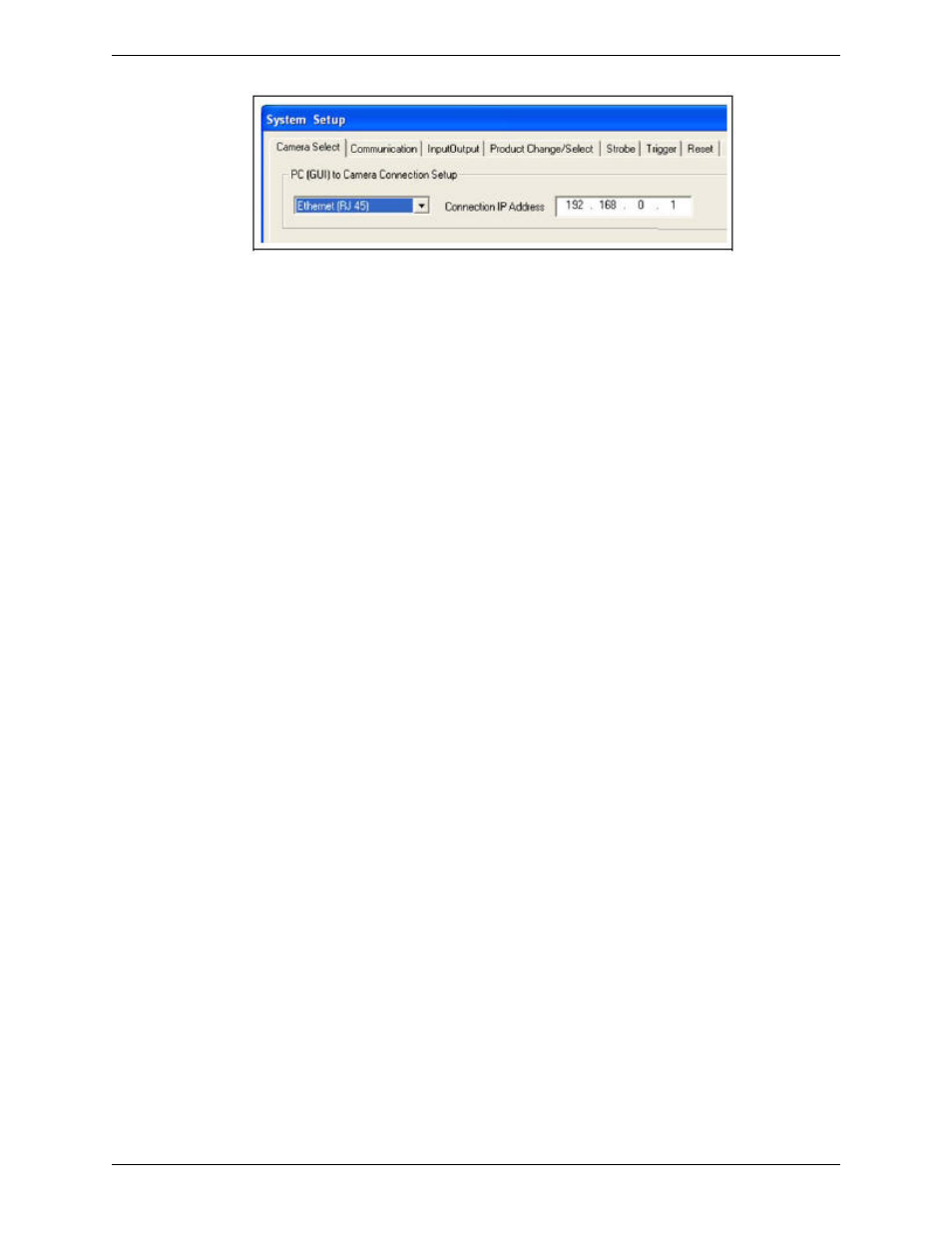
7. Verify PC configuration.
• Ethernet connection: IP address of PC is 192.168.0.2.
• Serial connection: A dial-up network has been established, and the network is a point-to-point protocol (PPP).
8. Power up the hardware and verify that the Error LED turns off.
25
Minneapolis, MN USA
Banner Engineering Corp.
Getting Started
2/2010