Rockwell Automation MPMA Integrated Multi-Axis Linear Stages User Manual
Page 50
50
Rockwell Automation Publication MPMA-UM001B-EN-P - November 2010
Chapter 6 Configuration Guidelines
Conversion
Positioning Mode
Linear
Conversion Constant
200 drive counts / 1.0 mm
5080 drive counts / 1.0 in.
Hookup
(1)
Test Increment
70 mm, min for Ultra3000 drive
20 mm Kinetix 2000 drive
20 mm Kinetix 6000 drive
2.76 in. min for Ultra3000 drive
0.787 in. Kinetix 2000 drive
0.787 in. Kinetix 6000 drive
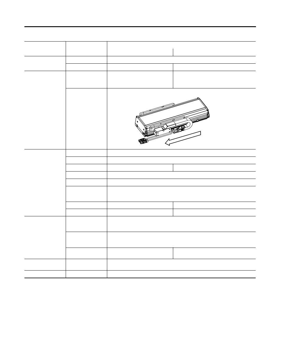
Drive Polarity
Positive
Homing Mode Active
Position 0
(or
programmable)
Offset
5 mm, min
0.2 in., min
Sequence Torque
Level-to-Marker
Direction Reverse
Bi-directional
Torque Level
80%, min
Greater if the system friction, force, or weight exceeds 80% of the Continuous Force Rating at any
point in the range of motion
Speed 50 mm/s
1.97 in./s
Return Speed
10 mm/s
0.39 in./s
Limits
Hard Travel Limits
Check if hardware limits are in use.
Use Motion Analyzer to determine the maximum stopping distance in your application to set
Negative and Positive Limits
Soft Travel Limits
Check
Use Motion Analyzer to determine the maximum stopping distance in your application to set
Negative and Positive Limits
Position Error
Tolerance
(2)
10 mm
0.394 in.
Gains
Feedforward Velocity
Gain
100%
Tune
Velocity Feedforward
(3)
Check
(1) The Command and Feedback test, accessed from the Hookup tab, does not verify the Hall Sensor wiring to a Kinetix 2000 or a Kinetix 6000 drive. The wire colors and
continuity for the Hall signals must be manually verified.
(2) Using Auto-tune will reset this parameter to the default value.
(3) Using Velocity Feedforward will reduce position error during motion.
Axis Properties Tab
Parameter
Entry/Selection, with applicable distance unit settings
Metric
English
(+)
(-)
Positive Direction