Rockwell Automation MPMA Integrated Multi-Axis Linear Stages User Manual
Page 105
Rockwell Automation Publication MPMA-UM001B-EN-P - November 2010
105
Accessories
Appendix B
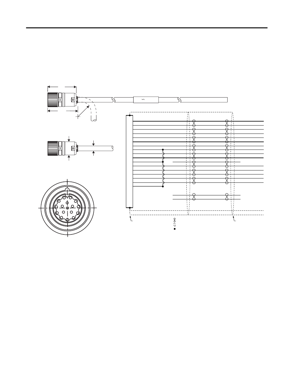
Feedback Cable Dimensions, Pinout, and Schematic
(2090-XXNFMF-Sxx)
You can use a cable length of up to 10 m (32.8 ft) for MPAS-
xxxxxx-ALMxxx
and up to 30 m (98.4 ft) for MPAS-
xxxxxx-Vxxxxx.
1
Bend radius (BR) is the specified minimum bend radius for cable assemblies. For standard cable, BR is a one-
time flex application. Flex cables have a much higher BR to withstand flex applications.
54
(2.1)
57
(2.2)
99
(3.9)
10
(0.4)
26
(1.0)
Dimensions are in mm (in.)
Start of
Bend Radius
Connector
Diameter
Cable
Diameter
Bend Radius
1
1
2
3
4
5
6
7
9
8
11
16
12
13
14
17
15
10
1
2
3
4
5
6
9
10
11
13
14
15
16
17
7
8
12
SIN+
SIN-
COS+
COS-
DATA+
DATA-
EPWR 5V
ECOM
EPWR 9V
TS+
TS-
S1
S2
S3
LIMIT+
LIMIT-
COM
N/C
N/C
N/C
N/C
28 AWG Black
28 AWG White/Black
28 AWG Red
28 AWG White/Red
28 AWG Green
28 AWG White/Green
16 AWG Grey
16 AWG White/Grey
22 AWG Orange
22 AWG White/Orange
28 AWG Blue
28 AWG White/Blue
28 AWG Yellow
28 AWG White/Yellow
28 AWG Brown
28 AWG White/Brown
28 AWG Violet
28 AWG White/Violet
28 AWG Drain
SIN+
SIN-
COS+
COS-
DATA+
DATA-
EPWR 5V
ECOM
EPWR 9V
TS+
S1
S2
S3
LIMIT+
LIMIT-
22 AWG Jumper
Connects 10, 12, 14
Motor connector backshell
shielded 360°
Customer must provide
360° shield to ground
connection
Denotes twisted pairing of wires
Denotes shield wire
Denotes wire splice or connection
(Heatshrink insulates wire-to-wire splices.)
N/C
N/C
22 AWG
22 AWG
22 AWG