Rockwell Automation MPMA Integrated Multi-Axis Linear Stages User Manual
Page 114
114
Rockwell Automation Publication MPMA-UM001B-EN-P - November 2010
Appendix C Interconnect Diagrams
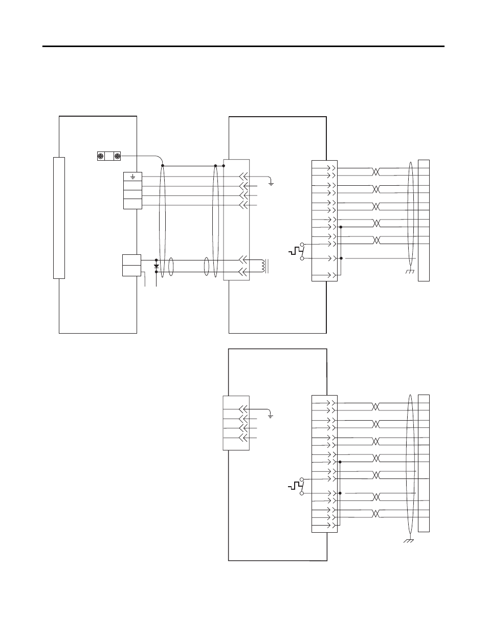
Figure 17 - Wiring Examples for MP-Series Integrated Linear Stages and Ultra3000
Drives
1
2
3
4
5
10
14
6
7
11
D
C
B
A
BR+
BR-
F
G
W
V
U
0
1
2
3
4
5
6
7
8
9
10
11
12
13
14
15
SIN+
SIN-
COS+
COS-
DATA+
DATA-
+5VDC
ECOM
GREEN
WHT/GREEN
GRAY
WHT/GRAY
BLACK
WHT/BLACK
RED
WHT/RED
3
4
5
6
1
2
9
10
14
12
+9VDC
TS+
ORANGE
WHT/ORANGE
11
13
4
3
2
1
Green/Yellow
Blue
Black
Brown
Black
White
GND
W
V
U
GND
Shield
W
V
U
D
C
B
A
TS-
COM
BLUE
AM+
AM-
BM+
BM-
IM+
IM-
+5VDC
ECOM
BLUE
WHT/BLUE
GREEN
WHT/GREEN
GRAY
WHT/GRAY
BLACK
WHT/BLACK
RED
WHT/RED
1
2
3
4
5
10
14
6
12
TS-
S1
–
TS+
ORANGE
WHT/ORANGE
11
S2
S3
COM
YELLOW
WHT/YELLOW
13
8
3
4
5
6
1
2
14
15
16
17
12
11
13
9
10
BRK -
BRK+
43
44
+24V
COM
User Supplied
24V dc (1.0A max)
Note 5
BALL SCREW STAGES WITH
HIGH RESOLUTION FEEDBACK
MPAS-A/Bxxxx-V05SxA and
MPAS-A/Bxxxx-V20SxA
2090-XXNPMF-xx Sxx
Motor Power Cable
Note 3
Thermostat
Three-Phase
Motor Power
Brake
ULTRA3000
DIGITAL SERVO DRIVE
Note 2
Cable Shield
Clamp
Note 1
Motor Power
(TB1) Connector
Control Interface
(CN1) Connector
Motor Feedback
(CN2) Connector
2090-XXNFMF-Sxx Feedback Cable
Notes 3, 4
Motor
Feedback
Motor Feedback
(CN2) Connector
DIRECT DRIVE STAGES WITH
INCREMENTAL FEEDBACK
MPAS-A/Bxxxx-ALMx2C
Thermostat
Three-Phase
Motor Power
Motor Feedback
(CN2) Connector
2090-XXNFMF-Sxx Feedback Cable
Notes 3, 4
Motor
Feedback
Refer to Low Profile Connector
illustration (lower left)
for proper grounding technique.
2090-XXNPMF-xxSxx
Motor Power Cable
connects to Motor Power (TB1)
and Cable Shield Clamp
as shown above