Connections for the 1797-oe8h module -13 – Rockwell Automation 1797-OE8H FLEX Ex HART Analog Modules User Manual User Manual
Page 65
Publication 1797-6.5.3 - March 2006
How to Install Your FLEX Ex Analog Modules 3-13
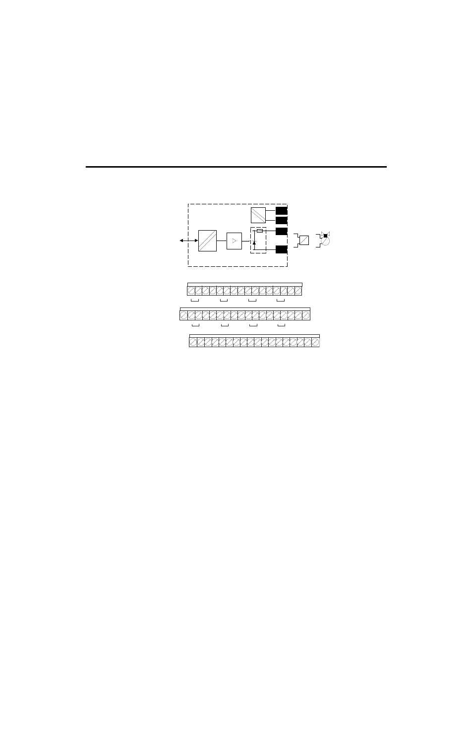
Connections for the 1797-OE8H Module
1. Connect the individual output wiring to (+) terminals (0, 4, 8, 12) on the
0 to 15 row (A) and on the 16 to 33 row (B) (terminals 17, 21, 25, 29) as
indicated in the table below.
2. Connect the associated output to the corresponding (-) terminal (1, 5, 9,
13) on the 0 to 15 row (A), and on the 16 to 33 row (B) (terminals 18,
22, 26, 30) for each input as indicated in the following table.
3. Connect +V dc power to terminal 34 on the 34 to 51 row (C).
4. Connect -V to terminal 35 on the 34 to 51 row (C).
5. If continuing power to the next terminal base unit, connect a jumper
from terminal 50 (+V) on this base unit to terminal 34 on the next base
unit.
6. If continuing common to the next terminal base unit, connect a jumper
from terminal 51 (-V) on this base unit to terminal 35 on the next base
unit.
flexbus
Bus
uC
+V
-V
+
-
power
supply
4 to 20mA
actuator
4 to 20mA
valve
41441
41440
Row A
Row B
Row C
ch0
ch1
ch2
ch3
+V
+V
-V
-V
0
1
2
3
4
5
6
7
8
9
10 11 12 13 14
15
16
17 18 19
20 21 22 23 24 25 26 27 28 29 30 31
32 33
34
35 36 37
38 39 40 41 42 43 44 45 46 47 48 49
50 51
+
+
+
+
-
-
-
-
ch4
ch5
ch6
ch7
+ -
+ -
+ -
+ -
No connections allowed to terminals 2, 3, 6, 7, 10, 11, 14, 15, 19, 20, 23,
24, 27, 28, 31, 32, 36, 37, 38, 39, 46, 47, 48, 49
1797-OE8H Module