Bulletin 284, continued – Rockwell Automation 284D ArmorStart - Safety Version - User Manual User Manual
Page 213
Specifications
A-9
Bulletin 284, Continued
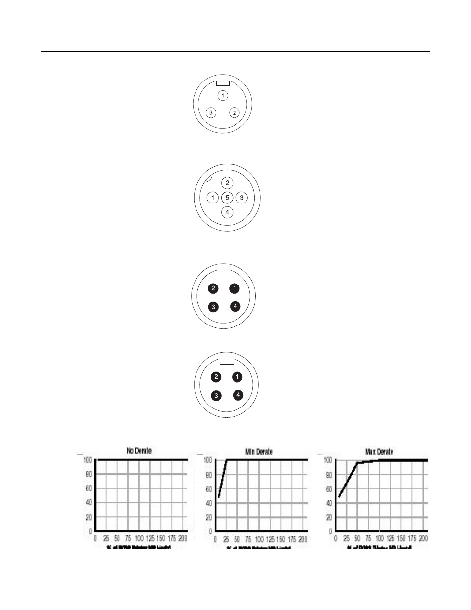
Figure A.15 External Connections for Dynamic Brake Connector
Figure A.16 External Connections for 0…10V Analog Input
Figure A.17 Safety Monitor Input (SM1/SM2)
Figure A.18 External Connections for Safety Input Power (A1/A2)
Overload Curves
Pin 1: GND
- Green/Yellow
Pin 2: BR+
- Black
Pin 3: BR-
- White
Pin 1: 10V DC
Pin 2: 0…10V Input
Pin 3: Analog Common
Pin 4: Analog Output
Pin 5: RS485 Shield
Pin 1: SM2- White
Pin 2: SM1 - Brown
Pin 3: N/C- No connection
Pin 4: N/C- No connection
Pin 1: M - White
Pin 2: A1 - Brown
Pin 3: P - Black
Pin 4: A2 - Blue
% of P132 (Motor NP Hertz)
% of P132 (Motor NP Hertz)
% of P132 (Motor NP Hertz)
% of P133 (Motor OL Current)
% of P133 (Motor OL Current)
% of P133 (Motor OL Current)
This manual is related to the following products: