Slave, safe stop mode, Figure 29 - cascaded connections – Rockwell Automation 21G PowerFlex 750-Series AC Drives Reference Manual User Manual
Page 98
98
Rockwell Automation Publication 750-RM001F-EN-P - February 2012
Chapter 8
Slave Modes for Multi-axis Cascaded Systems
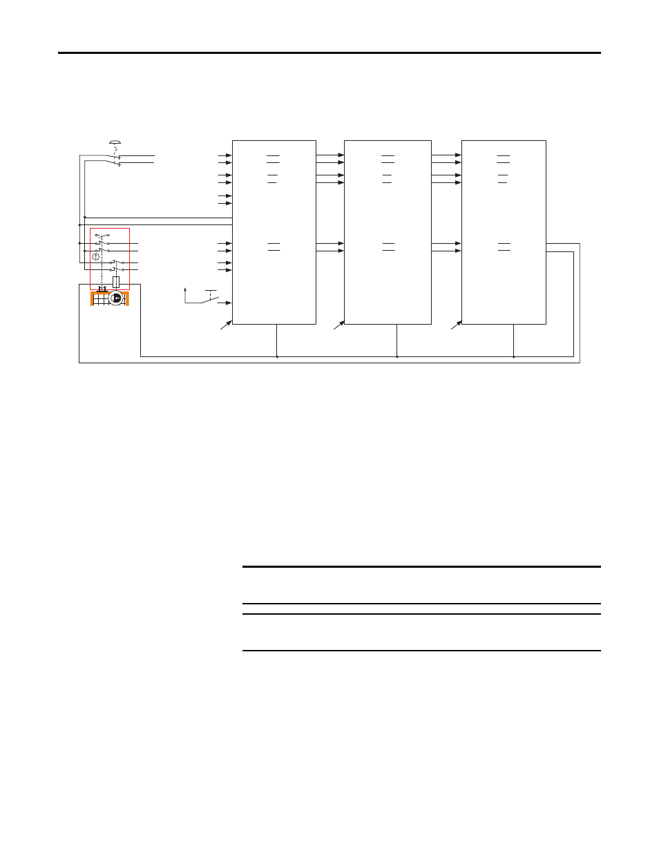
Figure 29 - Cascaded Connections
The inputs from the safety switches are monitored by the first safety option,
which is the master. A Safe Limited Speed Reset detected by the first safety
option is cascaded to the subsequent safety options via the SLS_Out to SLS_In
chain. Although all units can be configured for any reset type, we recommend
using automatic reset in all slave units to follow the master units reset type.
Any fault or transition of the SS_In input to OFF is detected by the first safety
option and initiates the configured P45 [Safe Stop Type] to all of the safety
options via the SS_Out to SS_In chain.
Any fault in a slave safety option initiates the configured P45 [Safe Stop Type]
only to that safety option and to slave safety options further down the chain.
Slave, Safe Stop Mode
When properly configured for Slave, Safe Stop mode, the safety option performs
the same functions as Safe Stop except that the safety option regards the Door
Monitor input as a Door Control output from an upstream axis, and performs a
logical AND with its internal Door Control signal to form the cascaded Door
Control output. This makes sure that the Door Control output commands the
door to unlock only if all units command the door to unlock.
Feedback
A2
24V DC
A2
A2
S34 Reset_In
S12 SS_In_0
S22 SS_In_1
S52 SLS_In_0
S62 SLS_In_1
S32 DM_In_0
S42 DM_In_1
S11 Pulse_Source_0
S21 Pulse_Source_1
SS_Out_0 34
SS_Out_1 44
SLS_Out_0 68
DC_Out_0 51
DC_Out_1 52
SLS_Out_1 78
Feedback
X32 LM_In_0
X42 LM_In_1
S34 Reset_In
S12 SS_In_0
S22 SS_In_1
S52 SLS_In_0
S62 SLS_In_1
S32 DM_In_0
S42 DM_In_1
SS_Out_0 34
SS_Out_1 44
SLS_Out_0 68
DC_Out_0 51
DC_Out_1 52
SLS_Out_1 78
S34 Reset_In
S12 SS_In_0
S22 SS_In_1
S52 SLS_In_0
S62 SLS_In_1
S32 DM_In_0
S42 DM_In_1
SS_Out_0 34
SS_Out_1 44
SLS_Out_0 68
DC_Out_0 51
DC_Out_1 52
SLS_Out_1 78
Feedback
12
22
34
11
21
33
A1
A2
42
41
52
51
S72 ESM_In_0
S82 ESM_In_1
Safe Stop Input
Safe Limited Speed Input
Enabling Switch Monitor Input
Manual Reset
First Axis
Feedback
Second Axis
Feedback
Third Axis
Feedback
Middle Axis
(Slave)
Axis 2
First Axis
(Master)
Axis 1
To Door
Control
Solenoid
Auto
Reset
Auto
Reset
Last Axis
(Slave)
Axis 3
Lock Monitor Input
Door Monitor Input
TLS3-GD2
440G-T27260
Power to Release
IMPORTANT
Safe Stop monitoring is not initiated for non-faulted units earlier in the
cascaded chain.
IMPORTANT
The safety reaction time for a cascaded system includes the sum of the reaction
times of each safety option in the chain.