Slave, safe stop wiring examples – Rockwell Automation 21G PowerFlex 750-Series AC Drives Reference Manual User Manual
Page 101
Rockwell Automation Publication 750-RM001F-EN-P - February 2012
101
Slave Modes for Multi-axis Cascaded Systems
Chapter 8
Slave, Safe Stop Wiring
Examples
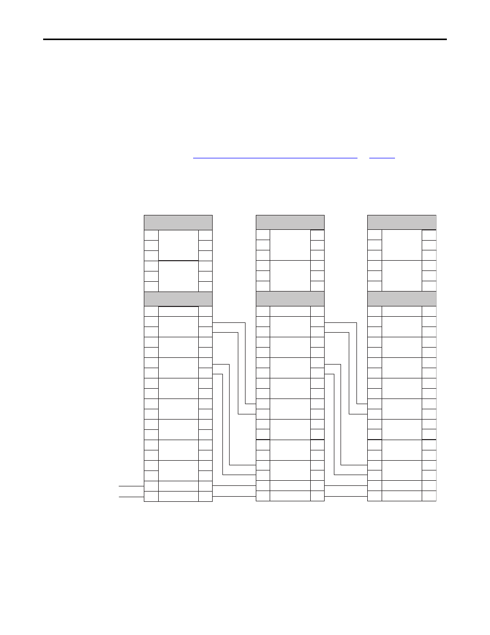
These examples show two different Slave, Safe Stop configurations.
The first example shows the safety option configured as a cascaded middle unit
via the P20 [Cascaded Config] parameter (Multi Mid). It has SS_In and DM_In
input connections from the previous upstream safety option, as well as SS_Out
and DC_Out output connections to the next downstream safety option. This
unit is configured with automatic reset so it follows the function of the previous
axis.
Safe Stop with Door Monitoring Wiring Example
for an example
of a first (master) unit.
Figure 30 - Slave, Safe Stop, Middle Unit
GND
S11
S11
S11
S21
S21
S21
TEST_OUT_0
TEST_OUT_1
+24V DC
TB1
TB2
S11
S11
S11
S21
S21
S21
A1
S12
S22
S72
S82
S52
S62
S32
S42
X32
X42
34
44
68
78
51
52
S34
A2
+24V
24V_COM
SS_IN_CHx
ESM_IN_CHx
SLS_IN_CHx
DM_IN_CHx
LM_IN_CHx
SS_OUT_CHx
SLS_OUT_CHx
DC_OUT_CHx
RESET_IN
A1
S12
S22
S72
S82
S52
S62
S32
S42
X32
X42
34
44
68
78
51
52
S34
A2
S11
S11
S11
S21
S21
S21
TEST_OUT_0
TEST_OUT_1
TB1
TB2
S11
S11
S11
S21
S21
S21
A1
S12
S22
S72
S82
S52
S62
S32
S42
X32
X42
34
44
68
78
51
52
S34
A2
+24V
24V_COM
SS_IN_CHx
ESM_IN_CHx
SLS_IN_CHx
DM_IN_CHx
LM_IN_CHx
SS_OUT_CHx
SLS_OUT_CHx
DC_OUT_CHx
RESET_IN
A1
S12
S22
S72
S82
S52
S62
S32
S42
X32
X42
34
44
68
78
51
52
S34
A2
Previous Upstream Axis
Safety Option Terminals
Next Downstream Axis
Safety Option Terminals
Middle Axis
Safety Option Terminals