Pfd and pfh data, Safe state, Pfd and pfh data safe state – Rockwell Automation 21G PowerFlex 750-Series AC Drives Reference Manual User Manual
Page 19
Rockwell Automation Publication 750-RM001F-EN-P - February 2012
19
Safety Concept
Chapter 1
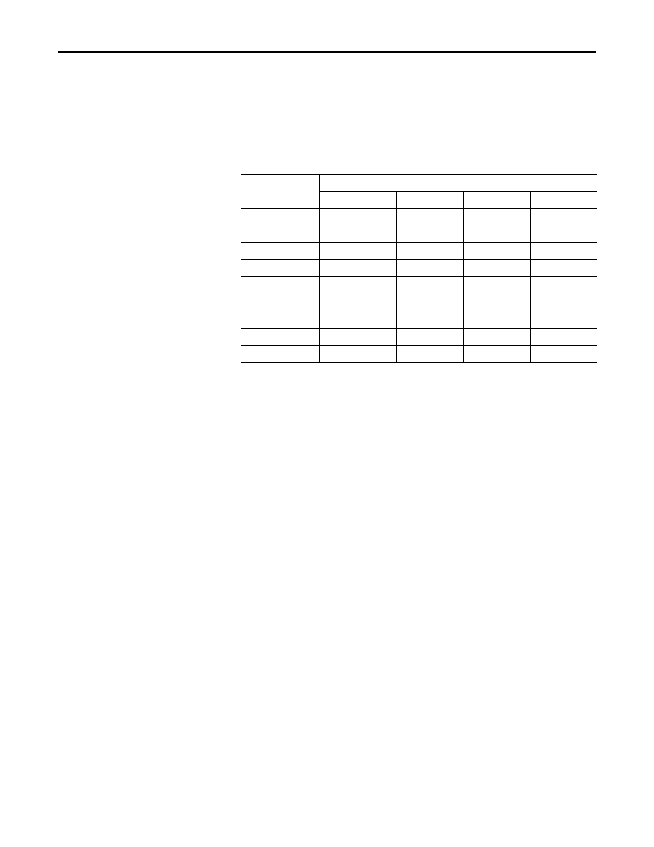
PFD and PFH Data
These PFD and PFH calculations are based on the equations from Part 6 of EN
61508 and show worst-case values.
This table provides data for a 20-year proof test interval and demonstrates the
worst-case effect of various configuration changes on the data.
Table 1 - PFD and PFH for 20-year Proof Test Interval
Safe State
The Safe State encompasses all operation that occurs outside of the other
monitoring and stopping behavior defined as part of the safety option. In
addition, configuration takes place in the Safe State. While the safety option is in
the Safe State, all safety control outputs, except the Door Control (DC_Out)
output, are in their safe state (de-energized). The Door Control (DC_Out)
output will be in either the locked state or in the de-energized state depending
upon the condition that resulted in the safe state.
When you cycle power, the safety option enters the Safe State for self-testing. If
the self-tests pass and there is a valid configuration, the safety option remains in
the Safe State until a successful request for safe speed monitoring occurs.
If a Safe State fault is detected, the safety option goes to the Safe State. This
includes faults related to integrity of hardware or firmware.
For more information on faults, refer to
.
Attribute
Value
Drive Frames 1…7
Drive Frame 8
Drive Frame 9
Drive Frame 10
PFD
2.35E-4
5.83E-4
4.67E-4
5.58E-4
PFH
2.67E-9 1/h
6.75E-9 1/h
5.33E-9 1/h
6.38E-9 1/h
SFF
99.5%
98.4%
98.2%
98.2%
DC
High
Medium (98%)
Medium (98%)
Medium (98%)
SIL CL
3
3
3
3
PL
e
e
e
e
CAT.
4
4
4
4
HFT
1 (1oo2)
1 (1oo2)
1 (1oo2)
1 (1oo2)
PTI (Proof Test Interval)
20 years
20 years
20 years
20 years